
|
| |
|
Строительный блокнот Introduction to electronics introduction to power processing The field of power elettronits is coiit;emed with the pr(x;essing of electrical power using elettronit devices [1-7]. The key element is the swilchiiig coiivenei; ilkistrated in Fig. 1.1. In general, a switching converter ttmtains power input iind control input ports, and a power output port. The raw input power is proces.sed as specified by the control input, yielding the conditioned output power. One of .several basic functions can be performed [2]. In a dc-dc coiiVLnei; the dc input voltage is converted to a dt output voltage having a larger or smaller magnitude, possibly with opposite polarity or with isolation of the input and output ground references. In an ac~dc reclifier. an ac input voltage is rectified, producing a dc output voltage. The dc output voltage and/or nc input current wavefomi may be controlled. The inverse pr[x;ess, dc-ac inversion, involves transforming a dc input voltage into an ac output voltage of controllable magnitude and frequency. Ac-ac cydoconversion involves converting an ac input voltage to a given ac output voltage of controllable magnitude and frequency. Control is invariably required. It is nearly always desired to produce a well-regulated output
Ромг input Fig. 1.2 A cutltroller is generally lequired, Feedforward Swilchhig converter Power output
Feedback [ Reference voltage, in the presence of variations in the input voltage and load t;urrent. As illustrated in Fig. 1.2, a controller blotk is an integral part of any power processing system. High efficiency is essential in any power processing application. The primary reason for this is usually not the desire to save money on ones electric bills, nor to conserve energy, in .spite of the nobility of such pursuits. Rather, high efficiency converters are necessary because construction of low-efficiency converters, producing substantial output power, is impractical. The efficiency of a converterhaving output power /цщ and input power P. is (1.1) The power lost in the converter is p, ..=p, -p , (1.2) Equation (1.2) is plotted in Fig. 1.3. In a converter that has an efficiency of 50%, power Pfg is dissipated by the converter elements and this is equal to the output power, Pj. This power is converted into heat, which must be removed from the converter. If the output power i.s substantial, then so is the loss power. This leads to a large and expensive cooling system, it causes the electronic elements within the converter to operate at high temperature, and it reduces the system reliability. Indeed, at high output powers, it may be impossible to adequately cool the convertereleraents using current technology. Increasing the efficiency is the key to obtaining higher output powers. For example, if the converter efficiency is 90%, then the converter loss power is equal to only 1 1% 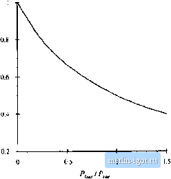 Kig. 1,3 Convener power loss vs. efficiency. I! liitwduciim !o Fomr Pmcessing  Kig. 1.4 A goal of currem converter technology is to construct conveners of small size and weight, which process substantial power at high efficiency. of the output power. Efficiency is a good measure of the success of a given converter technology. Figure 1.4 illustrates a converter that processes a large amount of power, with very high efficiency. Since very little power is lost, the converter elements can be packaged with high density, leading to a converter of small size and weight, and of low temperature rise. How can we build a circuit that changes the voltage, yet dissipates negligible power? The various conventional circuit elements are illustrated in Fig. 1.5. The available circuit elements fall broadly into the classes of resistive elements, capacitive elements, magnetic devices including inductors and tnmsformcrs, semiconductor devices operated in the linear mode (for example, as class A or class В amplifiers), and semiconductor devices operated in the switched mode (such as in logic devices where transistors operate in either saturation or cutoff). In conventional signal processing applications, where efficiency is not the primary concern, magnetic devices are usually avoided wherever possible, because of their large size and the difficulty of incorporating them into integrated circuits. In contrast, capacitors and magnetic devices are important elements of switching converters, because ideally they do not consume power. It is the resistive element, as well as the linear-mode semiconductor device, that is avoided [2]. Switched-mode semiconductor devices are also employed. When a semiconductor device operates in the off state, it.s current i.s zero and hence its power dissipation is zero. When the semiconductor device operates in the on (saturated) state, its voltage drop is small and hence its power dissipation is also small. In either event, the power dissipated by the semiconductor device is low. So capacitive and inductive elements, as well as switched-mode semiconductor devices, are available for synthesis of high-efficiency converters. Let us now consider how to construct the simple dc-dc converter example illustrated in Fig. 1.6. The input voltage is 1(X) V. It is desired to supply 50 V to aneffective 5 Q load, such that the dc load current is 10 A. Introductory circuits textbt)oLs describe a low-efficiency method to perform the required function: the vt)ltage divider circuit illustrated in Fig. 1.7(a). The dt~dc converter then consists simply of a Resistors Capacitors innr Magnetics Linear-mode Switcked-mode Semiconductor devices Fig. I.S ]>evi[:e!; iiviiilablf tothe circuit designer [2]. |
|||||||||||||||||||||