 | |
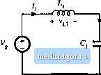
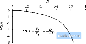
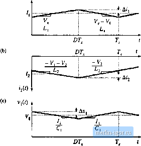
Строительный блокнот Introduction to electronics   ТПЛГ Fig. 2.21 Cuk coiivcreur circuit: (a) while awitch is in position 1. (b) wliilc switch is in po.sitioii 2. We next assume that the switching ripple maguitude.s in ifi), Jj(f), Vj(0, and vCOare small compared to their respective dc components /j, fj, Vj, and Vj.We can therefore make the small-ripple approximation, and Eq. (2.48) becomes (2.49) During the second subinterval, with the switch in position 2, the converter circuit elements are connected a.s in Fig. 2.21(b). The inductor voltages and capacitor currents are: V12 = - 1э (2.50) We again make the smali-rippie approximation, and hence Eq. {2.50) becomes ici = /1 , (2.51) Equations (2.49) and (2.51) are used to sketch the inductor voltage and capacitor current waveforms in Fig. 2.22. The next step is to equate the dc components, or average values, of the waveforms of Fig. 2.22 2.4 Uii Convener Exaniph Fig. 2.22 Cjk convener wavefoiins: (a) inducior voltage v, [(/), tb) inductor voltage vj2(0, (c) capacitor curi-CLit (.,(/), (d) capacitor cuirent ((-2(0 (b) v (f) h-V/R (=0) to zero, to find the steady-state conditions in the converter. The results are: (2.И) Solution of this system of equations for the dc components of the capacitor voltages and inductor currents leads to Lf s f - D i - - r- d r (2.53) The dependence of the dc output voltage Vj on the duty cycle D is sketched in Fig. 2.23. The inductor current waveforms are sketched in Fig. 2.24(a) and 2.24(h), and the capacitor Fig, Z23 Dt tonvefsion ratio m(d) =- V/V of the Cuk CMivcrter,  voltage waveform vU) is .sketched in Fig. 2.24(c). During thefirst.suhinterval.the .slope.s of the waveforms are given by dt ~ dijt) v,Ji) - V, - V; (2.54) Equation (2.49) lias been u.sed here to substitute for the values of mi and Vr during the first subinterval. During the second interval, the slopes of the waveforms are given by l4g. 2,24 Cuk cnriveiiei waveftums: (a) inductor current i(r), (b) inductor СПГГЙ11Е fj(/), (c) capaciuii voltage V(/).  |