 | |
|
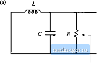
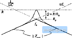
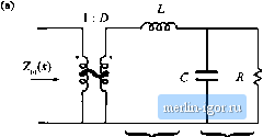
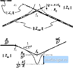
Строительный блокнот Introduction to electronics НА Graphical Cnitiiructinn of Convener Transfer Functions  Fig. 8.53 SmuU-signal model of the btick tonverter, with input impedance Z; (s> and output impedance Z l.j) explicitly defined, frequency asymptote has a -4f) dB/decade slope. At to = tO(j, has exact value R. while Z has exact value The ratio is then Wfjui ) ] = 1 Z ,(;ffi,) \\l\\ 2,(jffl(,) ]] = RIR - Q. So the filter transfer function Я has the same Criound Q as the impedance Z ,,. It now becomes obvious how variations in element values affect the salient features ofthe transfer function and output impedance. For example, the effect of increasing L is illustrated in Fig. 8.52. This causes the angular resonant frequency O),) to he reduced, and also reduces the Q-factor. GRAPHICAL CONSTRUCTION OF CONVERTER TRANSFER FUNCTIONS The small-signal equivalent circuit model ofthe buck converter, derived in Chapter 7, is reproduced in Fig. 8.53. I et us construct the transfer functions and terminal impedances of this converter, using the graphical approach ofthe previous section. The output impedance Z ,.i) is found with the d(,s) and vjs) sources set to zero; the circuit of Fig. 8.54(a) is then obtained. This model coincides with the parallel R-L-C circuit analyzed in Sections 8.3.3 and 8.3.4. As illustrated in Fig. 8.54(b), the output impedance is dominated by the inductor at low frequency, and by the capacitor at high frequency. At the resonant frequency/p, given by iTifUC (8.165) the output impedance is equal to the load resistance R. The Q-factor of the circtiit is equal to  2 ,()  Fig, 8.54 Construcii of buck convener output impcdntice 2Jx): (a) circuit model; (b) impedattee asymptotes.  <b) Z,(j) .......coC A L 2ПДС Л ............ In/LC  Fig. 8.5S Construclion of (he input impedance Z; {i) for the buck converter: (a) circuit model; (b) the individual resistor, inductor, and capacitor impedance magnitudes; (c) construction of the impedance magnitudes Z J and { ; (d) construction of II Z, , ](; (e) final result Z( Ij. ..,. c  (8.166) where (8,167) Thus, the circuit is lightly damped (high Q) at light load, where the value of Я is large. The converter input impedance is also found with the and v,(j) sources set to zero, as illustrated in Fig. 8.55(a). The input impedance is referred to the priinary side of the 1:D transformer, and is equal to = 2,(.,} + Z,(,) (8.168) where S.4 Graphica! Consrruclion of Convener Transfer Functions 315 Z,{s)sL (8,169) Z,W = fil; (Si ) We begin oonsiniedoii of (he impedance asymptoies corresponding to Eqs. (S.168) (o (8.170) hy constructing the individual resistor, capacitor, and inductor impedances as in Fig. S.55(b). The impedances in Fig. S.55 are constructed for the case ft > ,], As illu.strated in Fig. S.55(c), i 2, { coincide.4 with the inductor reactance uiL, The impedance Zj is asymptotic to resistance R at low frequencies, and to the capacitor reactance l/w6at high frequency. The resistor and capacitor irsymptotes intersect at corner frequency /, given by According to Ь]. (8.168), the input impedance Z, (s) is equal to die .series ctmibinatitm ofZ(j)and Z(s), divided by the square ofthe turns ratio D. The asymptotes for the series combination [Z,(,v) -(- Z2(.v)] are found by selecting the larger ofthe f and asymptotes. The J Z and Zj asymptotes intersect at frequency/(), given by Eq. (8.165). It can be seen from Fig. 8.55(c) that the seiies combination is dominated hy Zj for/<Уц, and by Z[ for/>. Upon scaling the [Z[{j) + Zis)] asymptotes by the factor 1/D, the input impedance asymptotes of Fig. 8.55(e) iire obtained. The zeroes of Z, (.v), at frequency/о, have the same -factor as the poles of Z ,Ci) [Eq. (8.166)]. One way to .see that this is true is to note that the output impedance tan be expressed as Z,(s)Z,(s) Z)Z,isf -Z,(i) + Z,(.v) D% is) Hence, we can relate toZ;,(ji) as follows: The impedances I] Z, j, Zj ], and Z, are illustrated in Fig, S.55(d), At the resonant frequency q, impedance Z has magnitude and impedance Zhas magnitude approximately equal to Wp.Tlie output impedance Zjjhas magnitude R. Hence, Eq. (8.173) predicts that the input impedance has the magnitude i.h- = (8.m) Atf-ff the asymptotes ofthe input impedance have magnitude Я()70. The deviation from the asymp-tote.s is theieft)re equal to Q = as illustrated in Fig. 8.55(e). The control-to-output transfer function 6r /j) is found with the 9(s) source set to zero, as in Fig. 8.56(a). This circuit coincides with the voltage divider analyzed in Section 8.3.5. Hence, G.Js) can be expressed as |