
|
| |
|
Строительный блокнот Introduction to electronics Fig. 8.56 Construction of the conlrol-to-output transfer function GJs) for the buck converter: (a) circuit modeh (b) relevant impeiJance asymptotes; (c) transferfunction Cj:j). 0>) (e) (it) 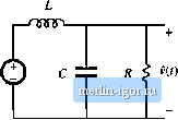 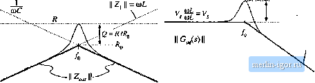 The quantities \\ Z \\ and \\ Z, (! tue constructed in Fig. 8.56(b). According to Ь]. (8.175), we can construct [ Gj(i) [ by finding tlte ratio of (( Z , and [[ Z, ((, and then scaliitg the result by V. Far f<f,j, II Zj, and II II are both equal to OiL and hence Z , / Z, is equal to 1. As illustrated in Fig. 8.56(c), the low-frequency asymptote of Ц has value V For/>/f I! 2, , 11 has asymptote У<ОС\ and IJ Z I) i s equal to(liL Hence, [ Z /1 Z, has asymptote UiiiLC, and the high-frequency asymp-tt>te of II Gj.s) II is equal to V/iHLC. The Q-factor of the two pt>les at f-fi, is again equal toR/Kf,. The line-to-output tran.sferfunction G,(s) is found with the d(s) sources .set to zero, as in Fig. 8.57(a). This circuit contains the same voltage divider as in Fig. S.56, and additionally contains the l:D transformer. The transferfunction 0(s) can be expressed as Fig. 8.57 The hne-to-output transfer function C(s) f[>c the buck converter: (a) circuit mode); (b) magnitude asymptotes. 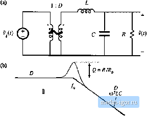 II Gis) s.5 Measureinen! of AC Transfer Funclions and Impedances Network Analyzer Itection source Magnitude Frequency 9 Output i-O- Measured inputs Input Input Data
- 134.7 Daia bus to computer Fig. SJ8 Key features add fudctio/ii of a network aiiaJyzer; sJiiiisoidal source of coHCiollablL- iiniijlittidc aud frequency, two input.s, and deterniination of relative itiagiiitude and plisise of tlic input conipuneiu.i al tlie injeaion frequency. (8.17fS) This expression is similar to Eq. (8.175), except for the .scaling factor of D. Therefore, the line-to-outpiit transfer function of Fig. 8.57(b) has the same shape as the control-to-output transfer function OJ,.i), 8.5 MEASUREMENT OF AC TRANSFER FUNCTIONS AND IMPEDANCES It is good engineering practice to ineasure the transfer functions of prototype converters and converter systems. Such an exercise can verify that the system has been cotjectly modeled and designed. Also, it is often useful to characterize iitdividual circuit elements through measurement of their terminal impedances. Small-signal at magnitude and phase raeasuremeitts tan he made using an instrument linown as a network analyzer, or frequency response analyzer. The key inputs and outputs of a basic network analyzer are illustrated in Fig, 8.58. The network analyzer provides a sinusoidal output voltage v. of controllable amplitude and freciuency. This signal can be injected into the system to be measured, at any desired locatitm. The network analyzer also has two (or more) inputs, and P, The return electrodes of v., Vy, and are internally ctmnected to earth ground. The network analyzer performs the function of a narrowband tracking voltmeter: it measures the components of and f at the injection frequency, and displays the magnitude and pha.se of the quantity v.A\- The narrowband tracking voltmeter feature is essential for switching converter measurements: otherwise, switching ripple and noise corrupt the desired sinusoidal signals and make accurate measurements impossible [Л]. Modern network analyzers can automatically sweep the frequency ofthe injection source v, to generate magnitude and phase Bode plots of the transfer function vfv. A typical test setup for measuring the transfer function of an amplifier is illustrated in Fig. 8.59. A potendometer, connected between a dc supply voltage V-,- and ground, is used to bias the Network Analyzer Irlton source blocking capacitor 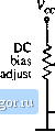 lipui Ittpui
-162.8 Device under test Fig, 8,59 Muamircmutii ula iranKter iiHlctiun. amplifier input to attain the correct quiescent operating point. The injection source voltage is coupled to the amplifier input terminals via a dc blocking capacitor. This blocking capacitor prevents the injection voltage source from upsetting the dc bias. The network analyzer inputs and are connected to the input and output terminals of the amplifier. Hence, the measured transferfunction is = f7(.v) (8.1771 Note that the bh}cking capacitance, bias potentiometer, and i, amplitude have no effect on the measured transfer function An impedance (!4.17Й) can be measured by treating the impedance as a transfer function froin current to voltage. For example, measurement of the output impedance of an amplifier is illustrated in Fig. 8.60. The quiescent operating condition is again established by a potentiometer which biases the amplifier input. The injection source Vj, is coupled to the amplifier output through a dc blocking capacitor. The injection source voltage v, excites a current in impedance У.. This current Hows into the output of the amplifier, and excites a |