
|
| |
|
Строительный блокнот Introduction to electronics Ihe following values: n = 2, = 4Я V, D = 03, Я = 5 fi, Z, = 250 iH, С = 100 fiF, R, = 1.2 Q. Label the numerical values of ihe constant asymptoies, all corner frequencies, ihe factor, and asymptote slopes. 8.9 Magnitude Bode diagram of an R-iC filter circuit. For the filter circuit of Fig. 8.66, construct the Bode plots for the magnitudes ofthe Thevenin-equivalem output impedance Z , and the transfer function (.() = fj/if,. Plot your results on semilog graph paper. Give approxiniate analytical expressions and numerical values for the important comer frequencies and asymptoies. Do all of the elements significantly 8l10 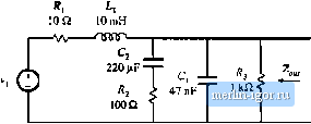 Fig. SM Piltercifcuitof Problem 8.9. Operational aniplifier filter circtiit. The op anip circuit shown in Fig. 8.67 is a practical realization of what is known as a PID amtroUer, and is sometimes used to modify the loop gain of feedback circuits to improve their performance. Using semilog graph paper, sketch the Bode diagram of the magnitude of the transfer function ij(j)/V[{j) of the circuit shown. Isabel all comer frequencies, flat asymptote gains, and asynipiote slopes, as appropriate, giving bodi analytical expressions and numerical values. You may assume that the op amp is ideal. 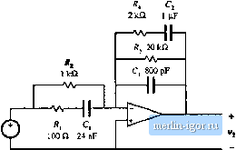 Fig. 8.67 Op-amp PID controller circuit. Problem 8.10, 8.11 Phase asymptotes. Construct the phase asymptotes for the transfer function visvis) of Problem S.IO, Label all break frequencies, flat asymptotes, and asynipiote slopes. 8.12 Construct the Bode diagram for the magnitude ofthe output impedance Z , of the network shown in Fig. 8.68. Give suitable analytical expressions for each asymptote, corner frequency, and g-factor, as appropriate. Justify any approximations that you use. The component values are: L, =100дН 1000 (*F L; = 16 mH 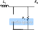 Fis. S.68 Filter Eietwoikol Problem Й. 12. S.13 8.14 8.1S The two Setljon input filter in the tirtuil of Fig. 8.69 shouid be designed sueh tiiiit its output impedance 2oi,( =0 meets certain input fitter design criteria, and hence it is desirable to construct the Bode plot finr the magnitude of Z,. Although this filtercontains sis reactive elements, can nonetheless be constructed in a relatively straightlorwtLrd mannerusing graphical construction techniques.The element v;ll-ues are: /., = 32 mil C, 32iF L;-40UfiM Cj = 6,KfiP f.,=:800;iH K, = II>Q l.=\iiH 2=1 Q Construct ii 11 using the algebra on the graph method. Give simple approximate analytical expressions fur all asymptotes and corner frequencies. It is desired thit 2!, be approximately equal lo 5 il at 500 Hz and 2,5 Q al I kHz. Suggest a simple wiiy to accomplish this by changing the value of one component. 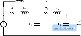 Fig. 8.69 Itiputfiltcrcircuitof Problem 8.13, Conslrucl the Bode pica of the magnitude of the output impedance of the filter illustrated in Fig. Fig. 8.70. Give approximate analytical expressions for each corner frequency. No credit will be given for computer-generated plots. A certain open-loop back-boost Converter contains an inpul filler. Its small-signal ac model is shown in Fig. 8.71, and the element values are specified below. Construct the Bode plot for the magnitude of the converter output impedance [ У , {) Ij. Label the values of all important corner frequencies and asymptotes. 0 = 0.6 L=150ftH Л-ЙУ Г=16мГ С = 0.33 ;tl Q = 2200 i. = 25 дН 1 Q JrtH 28 V -1--W i. 0.2 ;iH : 100 nF Д, 0.2 с tOitH -/VV- 10 fl 1 mH J C, lOOOjxF -p lOOnF C, lOOF d=. -r Fig. 8.70 Input filter circuit of Problems. 14. 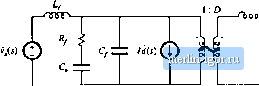 8.16  Fig. И.71 Small-signal model of a buck-boosi converter widi input filter, Problem 3.15. The srnall-.4ignal equations of the Watkins-Johnson converter operating in continuous conduction mode arc; L =- + {2V - V)r?tl> + (D - D)f/t) ,уг) = (0.-Я)ГМ + 2Мг) (a) Derive analytical expressions for the line-to-output transfer function and the control-to-outpuC transfer function GJf), (b) Derive analytital expressions for the salient features (dc gains, corner frequencies, and -fac tors) of the transfer functions Gjl-*) and Cl ). Express your results as fiintions of V, D. R. L. and C. (c) The converter opeiale.s al = 28 V, D = 0.25, Д = 28 il. С = 100 дР, L = 40O flV. Sketch the Bode diagram of the magnitude and phase of C,j). Label salient feaiures. 8.17 The element values in the buck converter of Fig. 7.ЙК are; Vj=120V 0 = 0.6 = 10Q fij = 2n f, = 550;iH C=100frF (a) Detennine an analyiital expression for ihe conirol-to-ouiput transfer function G (<;) of thi.s con- (b) Find analytital expressions for the salient features of GJji). (c) Construct magnitude and phase asymptotes iorG. Label the numerical values of all slopes and |