
|
| |
|
Строительный блокнот Introduction to electronics 2.5 Estimating the Отри! Voltage Ripple in Convmen Comaininjf Two-Pole Low-Paa Filters 31 dt ~ - L, dv,{t) ici(f) /, dt C, C, Equation (2.51) was used to substitute for the values of V; vyj i.j during the second subinterval. During the first subinterval. the quantities ([(f), ((O. and change by 2Д, - ЗД/, and - 2iV[, respectively. Tliese changes are equal to the slopes given in Eq. (2.54), multiplied by the sub-interval length DT yielding Ai, = iDr, (2.56) The dc relationships, Eq. (2.53), can now be used to simplify these expressions and eliminate Vj, Vj, and /i, leading to Д<г= (2.57) A\>, = IDRC, These expressions can be used to select values of L L and C, such that desired values of switching ripple magnitudes are obtained. Similar arguments cannot be used to estimate the switching ripple magnitude in the output capacitor voltage Vj(t)- According to Fig. 2.22(d), the current icit) is continuous:unlike ili lZ and cf the capacitor current (.O is nonpulsating. If the switching ripple of iU) is neglected, then the capacitor current /(jCOJoes not contain an ac component. The sraall-ripple approximation then leads to the conclusion that the output switching ripple Av is zero. Of course, the output voltage switching ripple is not zero. To estimate the magnitude of the output voltage ripple in this converter, we must not neglect the switching ripple present in the inductor current (,(г), since this current ripple is the only source of ac current driving the output capacitor Cj. A simple way of doing this in the converter and in other similar converters is discussed in the next section. 2.5 ESTIMATINC THE OUTPUT VOLTAGE RIPPLE IN CONVERTERS CONTAINING TWO-POLE LOW-PASS FILTERS A case where the small ripple approximation is not useful is in converters containing two-pole low-pass filters, such as in die output of the Cuk converter (Fig. 2.20) or the buck converter (Fig. 2.25). For these 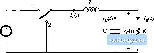 Fig, 2,25 The ЬиЛ converter eontains a two-pole output filter. converters, the small-ripple approximation predicts zero output voltage ripple, regardless of the value of the output filter capacitance. The problem is that the only component of output capacitor current in these cases is that arising from the inductor current ripple. Hence, inductor current ripple cannot be neglected when calculating the output capacitor voltage ripple, and a more accurate approximation is needed. An improved approach that is useful for this ca.se is to estimate the capacitor current wavefonn iC) more accurately, accounting for the inductor current ripple. The capacitor voltage ripple can then be related to the total charge contained in the positive portion of the 1(1) wavefonn. Consider the buck converter of Fig. 2.25. The inductor current waveform fjC/) contains a dc component / and linear ripple of peak magnitude Ali, as shown in Fig. 2.10. The dc component / must flow entirely through the load resistance R (why?), while the ac switching ripple divides between the load resistance R and the filter capacitor С In a well-designed converter, in which the capacitor provides significant filtering of the switching ripple, the capacitance С is chosen large enough that its impedance at the switching frequency is much smaller than the load impedance R. Hence nearly all of the inductor current ripple flows through the capacitor, and very little Hows through the load. As shown in Fig. 2.26, the capacitor current wavefonn iii) is then equal to the inductor current waveform with the dc component removed. The current ripple is linear, with peak value Ai, When the capacitor current is positive, charge is deposited on the capacitor plates and the capacitor voltage vjit) increases. Therefore, between the two zero-crossings of the capacitor current waveform, the capacitor voltage changes between its minimum and maximum extrema. The waveform is symmetrical, and the total change in is the peak-to-peak output voltage ripple, or 2uv. This change in capacitor voltage can be related to the total charge (/ contained in the positive Fig. 2,26 Output capac:it<r v>ltuge and current waveforms, for the buck converter in Fig. 2.25. 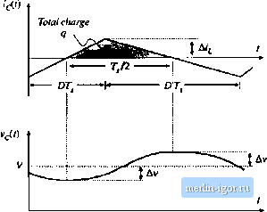 2.5 EstimaUng the Output Voltage Ripple in Conveners Containing Twa-Poie Low-Pass Filters Fig, 2.27 Estimating inductoi- current ripple when the inductor voltage wave-foini 15 continuous. Total flux lirJcage 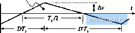 kit) portion ol the capacitor current waveform. By the capacitor relation Q - CV, il=C{2Av) (2.58) As illustrated in Fig. 2.26, the chaige q is the integral of the current waveform between its zeio CTOssings. For this example, the integral can be expressed as the area of the shaded triangle, having a height Ai,.. Owing to the symmetry of the current waveform, the zero crossings occur at the centerpoints of the and DT, subintervals. Hence, the base dimension of the triangle is TJ2. So the total charge q is given by (2.-59) Substitution of Eq. (2.58) into Eq. (2.59), and solution for the voltage ripple peak magnitude if yields (2.60) This expression can be used to select a value for the capacitance С such that a given voltage ripple Av is obtained. In practice, the additional voltage ripple caused by the capacitor equivalent series resistance (esr) must also be included. Similar arguments can be applied to inductors. An example is considered in Problem 2.9, in which a two-pole input filter is added to a buck converter as in Fig. 2.32. The capacitor voltage ripple cannot be neglected; doing so would lead to the conclusion that no ac voltage is applied across the input filter inductor, resulting in zero input current ripple. The actual inductor voltage waveform is identical to the ac portion of the input filter capacitor voltage, with linear ripple and with peak value, Av as illustrated in Fig. 2.27. By use of the inductor relation X - Li, a result similar to Eq. (2.60) can be derived. The derivation is left as a problem for the student. |