 | |
|
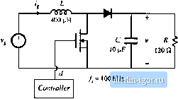
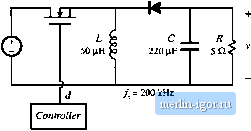
Строительный блокнот Introduction to electronics other important features. 9.19 Loss mechanisms in capacitors, such as dielectric loss and contact and foil resistance, can be modeled electrically using ал equivalent series resistance (esr). Capacitors whose dielectric materials exhibit a high dielectric constant, such as electrolytic capacitors, tantalum capacitors, and some types of multilayer ceramic capnciloi, typically exhibit relatively high esr. A buck converter contains a 1.6 mH inductor, and operates with a quiescent duty cycle of 0.5. Its output capacitor can be modeled as a 16 fiF capacitor in series with a 0.2 Q esr. The load resistance is 10 Я. The converter operates in continuous conduction mode. The quiescent input voltage is = 120 V. (a) Determine an analytical expression for the control-to-oatpat transferfunction ) of this converter. (b) Find analytical expressions for the salient features of (j(s). (c) Construct magnitude and phase asymptotes for (i,. Label the numerical values of all slopes and other important features. 8.19 Tlie LCC resonant inverter circuit contains the following transfer function: sC,R 1 + sRiCi + C2) + sLCi + juc (a) When C[ is sufficiently large, this transfer function can be expressed as an inverted pole and a qnadratic pole pair. Derive analytical expressions for the comer frequencies and Q-factor in this case, and sketch typical magnitude asymptotes. Determine analytical conditions for validiiy of your approximation. (b) When C2 is sufficiently large, the transfer function can be also expressed as an inverted pole and a quadratic pole pair. Derive analytical expressions for the corner frequencies and t-factor in this case, and sketch typical magnitude asymptotes. Determine analytical condidons for validity of your approximation in this case. (c) When C = and when the quadraiic poles have sufficiently high Q, then the transfer function can again be expressed as an inveried рю1е and a quadratic pole pair. Derive analytical expressions for the corner frequencies and (2-factor in this case, and sketch typical magnitude asymptotes. Determine analytical conditions for validity of your approximation in this case. 8J0 A two-section L-C filter has the following transfer functinn: 1 + .v The element values are: Я = 50 mfl C = 680 ilP Cj = 4.7 fiF Z, = 500 fill L = 50 fiH (a) Factor G{s) into approximate real and quadratic poles, as appropriate, Give analytical expressions for the salient features. Justify your approximation using the numerical element values. (b) Coiisiruct the magnitude and phase asympiotes of <7(.5). (c) It is desired to reduce the Q to 2, withont significantly changing the corner frequencies or other features of the response. It is possible to do this by changing only two element values. Specify how to accomplish this, 921 The boost converter of Fig. 8.72 operates in the continuous conducdon mode, with quiescent duty cycle D - 0.6. On semi-log axes, conslrutt the magnilude and phase Bode plots uf (a) the coQlri)l-to-oiJlpul iransfer funtlion Cfji). (1>) ihe line-(o-output imnsfer fiinttion (c) the oulpul impedance Ztv),and (d) ihe input impedance Z,p). On each plot, label the corner frequencies and asymptotes. Boost converter Fig. 8.72 Boo.4t converter of Problem 8.21.  d / = 200 kHz Controller 8.22 The forward converter of Fig. 8.73 operates in the continuous conduction mode, with the quiescent val- ues = 3S0 Vand F = 28 V. The transformer turns ratio is = 4.5, On semi-log axes, construct the magnitudeandphase Bode plots of (a) the control-to-output transfer function G J.v), and (b) the line-tc)-()utput transfer function ti-W- On each plot, label the corner frequencies and asymptotes. Hint: otherthan introduction of the turns ratio [/fr J, die transformer does not significantly affect the small-signal behavior of the forward converter. H- ЛППГ 500 (iH Controller J= 150 кНг Ftg, 8,73 Forward corvener of Problem 8.22. 8J3 The boost converter of Fig. 8.74 operates in the continuous conductiim mode, with the following quiescent values: - 120 V, 1 = 300 V, It is desired lo control the converter input current waveform, and hence it is necessary to determine the small-signal transfer func lion J(s) (a) Derive an analytical expression for j(s). Express all poles and zeioes in normalized standard forai, and give analytical expressons for the cnrner frequencies!, g-factor, and dc gain. (b) On semi-log axes, coiisiruct the Bode plot for the magnitude and pha.se of 6;,/s). Fig. S.74 Uooal coiiveitei of Problem 8.23.  8J4 The btick-boost converter of Fig. .75 operates in the continuous conduction mode, with the following quiescent values; = 48 V, V=-24Y On semi-log axes, constmct the magnitude and phase Bode plots of: (a) the control-to-outpui transferfunction G/.t), and (b) tbe output impedance (1). On each plot, label the corner frequencies and asymptotes as appropriate. Fig. Я.75 Buck-boost of ProbieiTi 8.24.  |