 | |
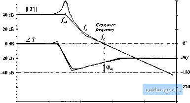
Строительный блокнот Introduction to electronics  -80 dB -40 dB/decade 100 Hi 100 Ш2 Fig. 9.7 Graphical constiiiction of 1/(1 + 7} . quencies is Л М Z Js) (9.16) The output impedance is also reduced in tnagtiitude hy a factor of l/ Г[ at frequencies helow the crossover frequency. At high frequencies (f >Q where ГЦ is small, then 1/(1 + Г) 1, and v(J) 2.Us) (9.17) This is the same as the original dtsturhance transferfunction and output impedance. So the feedback loop lias essentially no effect on the disturbance transfer functions at frequencies above the crossover frequency. STABILITY It is well known that adding a feedback loop can cause an otherwise stable system to become unstable. Even though the transfer functions of the original converter, Eq. (9.1), as well as of the кюр gain Г(.!), contain no right half-plane poles, it is possible for the closed-loop transfer functions ofEq. (9.4) to contain right half-plane poles. The feedback loop then fails to regulate the system at the desired quiescent operating point, and oscillations are usually observed. It is important to avoid this situation. And even when the feedback system is stable, it is possible for the transient response to exhibit undesirable ringing 9.4 Stahilin and overshoot. The stability problem is discussed in this section, and a method for ensuring that the feedback system is stable and well-behaved is explained. When feedback destabilizes the system, the denominator (1 t Д.*)) terms in Eq. (9.4) contain roots in the right half-plane (i.e., with positive real parts). If Г(.г) is a rational fraction, that is, the ratio /V(.r)/D(j) of two polynomial functions N(s) and D(.r), then we can write T(.t) D(s) 1 -b ns) + 7(1) D(s) t-t- ЛГ(л) 4 D(s) N(s) N{s) + D(i) D(s) (9.18) So T(s)/(l ( Дд)) and 1/(И-Г(.г)) contain the same poles, given by the roots of the polynomial {N{s) + D(s)). A brute-force test for stability is to evaluate (JV(.r) + £>(.?)), and factor the result to see whether any of the roots have positive real parts. However, for all but very simple loop gains, this involves a great deal of work. A simpler method is given by the Nyqtiist stability theorem, in which the number of right half-plane roots of (vV(.v) + D(.0) ean be determined by testing Д.т) [1,2]. This theorem is not disctissed here. However, a special case of the theorem known as the phase margin test is sufficient for designing most voltage regulators, and is discussed in this section. 9.4.1 The Phase IVlargin Test The crossover frequency f. is defined as the frequency where the magnitude ofthe loop gain is unity: r[j27t/,) =I=s.OdB (9-1) 60(ffiT  1 Hi 10 Hi 100 Hz 1 liHz to kHz 100 kHz Fig. 9.8 Magnitude and phase of ihe loop gain of a stable system. The phase inargin (p is posi;ive. 40dB 20 dB OdB -20 dB
0 -270 1 He 10 № 100 Hz 1 Шг lOkHi 100 kHi Hg. 9.9 Magnilude mid phase yf the loop gain of an unstable system, Tbe phase margin (p, is negative. To compute the phase margin (p, , the phase of the loop gain Tis evaluated at the crossover frequency, and 1S0° is added. Hence, Ф ,= ШГ + ZT{flnf,] (У,20) If there is exactly one crossover frequency, and if the loop gain T{s} ctmtain.s no right half-plane poles, then the quandties 1/(1 + T) and 77(1 + T) contain no right half-plane poles when the phase margin defined in Eq. (9.20) is positive. Thus, using a simple test on T(s), we can determine the stability of ГД1 + T) and 1/(1 + T). This is an easy-to-use design tool-we simple ensure that the phase of T is greater than -180° at the crossover frequency. When there are multiple crossover frequencies, the phase margin test may be ambiguous. Also, when Tcontains right half-plane poles (i.e., the original open-loop system is unstable), then the phase margin test cannot be used. In either case, the more general Nyquist stability theorem must be employed. The loop gain of a typical stable system is shown in Fig. 9.8. It can be seen that ZTQlTlD = -112 . Hence, ip. = 180 -112= +68. Since the phase margin is positive, 77(1 + T) and 1/(1 + T) contain no right half-plane poles, and the feedback system is stable. The loop gain of an unstable system is sketched in Fig. 9.9. For this example, ZT{j2Kfj) = -230. The phase margin is ф , = 180 - 230 = -50 . The negative phase margin implies that r/(l +T) and 1/(1 + T) each contain at least one right half-plane pole. 9.4,2 The Relationship Between Phase Margin and Closed-Loop Damping Factor How much phase margin is necessary. Is a worst-case phase margin of 1 satisfactory? Of course, good designs should have adequate design margins, but there is another important reason why additional phase margin is needed. A small phase margin (in T) causes the closed-loop transfer functions 77(1 + T) and 1/(1 +7) to exhibit resonant poles with high Q in the vicinity of the crossover frequency. The system transient response exhibits overshoot and ringing. As the phase margin is reduced these characteristics |
|||||||||||||||||||||||||||