
|
| |
|
Строительный блокнот Introduction to electronics Hence, T,Ss) = T(s) provided (hill ii Zj s. z, (9.66) So to obtain an accurate measurement, we need lo fjnd an injection point where loading is negligible over the range of frequencies to be measured, Other difficulties are encountered when using the method of Fig. 9.34. The most serious problem is adjustment of Ihedc bias using a potentiometer. The dc loop gain is typically very large, especially when a Р/controller is used. A small change in the dc component oivjf) can therefore lead to very large changes in the dc biases of some elements rn the system. So it is difficult to establish the correct dc conditions in the circuit. The dc gains may drift during the experiment, making the problem even worse, and saturation of the error amplifier is a common complaint. Also, we have seen that the gains of the converter can be a function of the quiescent operating point; significant deviation from the correct operating point can cause the measured gain to differ from the loop gain of actual operating conditions. 9.6.1 Voltage Injection An approach that avoids the dc biasing problem [3] is illustrated in Fig. 9.35. The voltage source vt) is injected between blocks 1 and 2, without breaking the feedback loop, Ac variations in vi,t) again excite variations in the feedback system, but dc bias conditions are determined by the circuit. Indeed, if v,(() coniains no dc component, then the biasing circuits of the system itself establish the quiescent operating point. Hence, the loop gain measurement is made at the actual system operating point. The injection source is modeled in Fig. 9.35 by a Thevenin equivalent network, containing an independent voltage source with source impedance Zj(j). The magnitudes of f and Zj are irrelevant in the determination of the кюр gain. However, the injection of does disrupt the loading of block 2 on block 1. Hence, a suitable injection point musl be found, where the loading effect is negligible. To measure the кюр gain by voltage injection, we connect a network analyzer to measure the transfer function from to vy The system independent ac inputs are set to zero, and the network analyzer sweeps the injection voitage v,(() over die intended frequency range. The measured gain is 4s} - (9,67) Block 1 (Sj(s)f,(i) H{s) i41<fLH-r-©-[Iii Btockl Ks) I 1 Zj(a) C;(i)v,(s)= ед Fig, 9 3S Measurement of loop gain by voltage injection. Let tis solve Fig. 9.35, to tompare the measured gain Tj,s) with the actual loop gain Д.г) given by (9.62). The error signal is The voltage v can be writlen i,(.() = -H(.0G2(.!)iJi> -v/.() = G,(s}v,(.v)-f(s)Z,(j) (9,69) where /(.i)Z,(j) is the voltage drop across the source itnpedance Z Substitution of Eq. (9.68) into (9.69) leads to - f is) = - P()Gj(i)ff(j)G,(j) - f(j)Z,(.v) But is lis): Therefore, Eq. (9.70) becomes ,{s) = <>p) G,(j)Cj(j)7/(j) + Z,(i) Zj(j) (9.70) (9.71) (9.72) Substitution ofEq. (9.72) into (9.67) leads to the following expression for the measured gain TJs)\ 7-,(i-) = Gi(i)C3(.v)W(.0 + (9.73) Equations (9.62) and (9.73) can be cotnbined to delermine the measured gain TJs) in terms ofthe actual loop gain T{s): T/.v} = T(.) (9.74) Tliu.s, T.Jys) can be expres.sed as the sum of two terms. The fir.st term is proportiotial to the acttial l[)op gain T{sX and is apprtixiniately equal to T(s) whenever Ц Ц l.The second term is not proportional to r(.i), and limits the mininitini r(.i) that can be measured with the voltage injection technique. If Z[/Zj is much smaller in magnitude than T{s), then the second term can 1эе ignored, and TJs) = T(s). At frequencies where 7\s) is smaller in magnitude than Z,/Z2,the ineasured data must be discarded. Thus, provided CD Zi(.() Z3(.f) (9.75) Fig. 9J6 Voltage injection example. Block i Blaekl 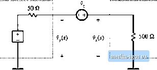 Again, nttte ttiat the valtte of the injectitm stiurce itnpedance Z, is iitelevaiit. As an example, consider voltage injection at the output of an operational ainplifier, having a 50 £2 output impedatice, which drives a 501) Q effective load. The .sy.steni in the vicinity of the injectioti point is tliustruted iti Fig. 9.36. So 7,(.v) = 50 Li atid ZC.v) = 500 П. The ratio 2,/Zj is 0.1, [)i-20 dB. Let us further .suppose that the actual lo[)p gain T{s) coutain.s poies at 10 Hz and l(X) kHz, with a dc gain of 80 dB. The actual loop gain magnitude is illustrated in Fig. 9.37. Voltage injection would result in measurement of TJs) given in Eq. (9.74). Note lhat Z,(.r) = 1.1 =>0.S3dB (9.76) Hence, for large ГЦ, the measured 7, deviates from the actual loop gain by less than 1 dB. However, at high frequency where ГЦ is less than -20 dB, the nieiisured gain diffei sigtiificatitiy. Appiirendy, 100 dB 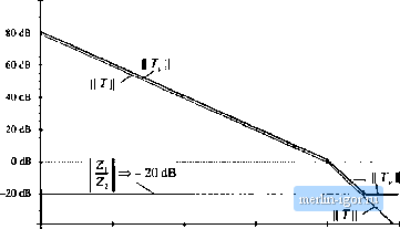 -*OdB tOOkHi tOtIz 100 tli I Mil lOkElz Fig. 9J7 Compari.son of measuitd loop gain 7 aiid actual loop gain 7; voitage injectiuri example. The measured gain deviates at high frequency. |