
|
| |
|
Строительный блокнот Introduction to electronics This page intentionally left blank Input Filter Design 10.1 INTRODUCTION 10.1.1 Conducted EMI Il is nearly always reqiiiref! tiial a filter be added at the power inpul uf a switching converter. By attenuating the switching harmDiiics that are present in the c[>nverter input cunent waveform, the input tfltei allows compliance with regulations that limit conductedeharomagneuc interference (EMI). The input filler cim also protect the converter and its load from transients that appeiir in the input voltage v(,t), thereby improving the system reliability. A siinple buck converter CAample is illustrated in Fig. 10.1. The converter injects the pulsating current ((r) of Fig. 10.1(b) into the power source vXf).The Fourier series of fj,(t) contains harmonics at multiples of the switching frequency, as follows: 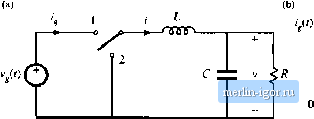 Fig. 10,1 Buck eotwerter exismple-. (a) circuit of power stage, (b) pulsating input eurreiil waveform. 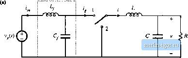 1 Input filter ] Fig, 10,2 Acldiliod ol n simple L-C luw-jiass (iHcr ю llie puwer input [cmiinals til die buck convener: (a) circuit. (b) iupiit cunent wtivcftirms. iJA = Dl + £ sin {knD] cos (hm) (10.1) In practice, the magnitudes of the higher-order harmonics can also be significantly affected by the current spike caused by diode reverse recovery, and also by the finite slopes of the switching transitions. The large high-frequency current harmonics of 1,(0 can interfere with television and radio reception, and can disrupt the operation of nearby electronic equipment. In consequence, regulations and standards exist that limit the amplitudes of the harmonic currents injected by a switching converter into its power source [1-8]. As an example, if the dc inductor current i of Fig. 10.2 has a magnitude of several Amperes, then the fundamental component ( = 1) has an rms amplitude in the vicinity of one Ampere. Regulations may require attenuation of this current to a value typically in the range 10 цЛ to 100 дА. To meet limits on conducted EMI, it is necessary to add an input filter to the converter. Figure 10.2 illustrates a simple single-section L-C low-pass filter, added to the input of the converter of Fig. 10.1. This filter attenuates the current harmonics produced by the switching converter, and thereby smooths the current waveform drawn from the power source. If the filter has transfer function H{s) = iJL, then the input current Fourier series becomes l;M = (0)11/ + Д I H(kj(u) I sin [knO) cos [itut + ZH(kM (10.2) In other words, the amplitude of each current harmonic at angularfrequency kdi is attenuated by the filter transfer function at the hartiiontc frequency, Hikjii)) . Typical requiretnents effecttveiy litiiit the current harmonics to have amplitudes less than 100 flA, and hence input filters are often required to attenuate the current amplitudes by SO dB or more. To improve the reliability of the system, input filters are sometimes required to operate normally when transients or periodic disturbances are applied to the power input. Such conductedsuscepti-biliry specifications force the designer to damp the input filter resonances, so that input disturbances do not excite excessive currents orvoltages within the filter or converter. |