
|
| |
|
Строительный блокнот Introduction to electronics A similar analysis shows that tiie converteroutput impedance is itot substantially affected by the input fdter wheit the following inequalities are satisfied: Z,*ZJ, and jpjj where is again as given in Table 10.1. The quantity Z(.0 is equal to the converter input impedance Z{s) underthe conditions that the converter otitput is shorted: Expressions for 2Д.т) for basic coitverters are also listed in Table 10.1. Similar impedance inequalities can be derived for the case of current-programmed converter.s [12,13], or converters operating in the discontinuous coitductitm mode. In [12], impedance inequalities nearly identical to the atxive equations were shown to guarantee that the input filter does not degrade transient response and stability in the current-programmed ca.se. Feedforward of the converter input voltage was suggested in [16]. 10.3 BUCK CONVERTER EXAMPLE Let us again consider the example of a simple buclt converter with L-C input filter, as illustrated in Fig. 10.8(a). Upon replacing the converter with its sinall-signal inodel, we obtain the equivalent circuit of Fig. 10.8(b). Lets evaluate Eq. (10.4) for this example, to find how the input filter mtxiifies the coiitrol-to-output transfer function of the converter. 10.3.1 Effect of Undamped Input Filter The quantities Zf(s) and Zp(s) can be read from Table 10.1, or can be derived using Eqs. (10.Й) and (10.7) as further described in Appendix C. Thequantity Zj(.v) is given by Eq. (10.Й). Upon setting d{i) to zero, the converter small signal model reduces to the circuit of Fig. 10.9(a). It can be seen that ZJs) is equal to the input impedance of the R-L-C filter, divided by the square of the turns ratio: (10.1Й) Construction of asymptotes for this impedance is treated in Section 8.4, with the results forthe numerical values of this example given in Fig. 10.10. The load resistance dominates the impedance at low frequency, leading to a dc asymptote of R/D = 12 Й, For the high-g case shown, 7,JJ((i) \\ follows the output capacitor asymptote, reflected through the square ofthe effective turns ratio, at intermediate frequencies. A series resonance occurs at the output filter resonant frequeticy given by For the element values listed in Fig. 10.8(a), the resonant frequency is = 1.6 kHz. The values of the asymptotes at the resonant frequency /(, are given by the characteristic impedance f?(j, referred to the Input filter Converter -4-ПППП- i 330 цн с, 470 nF* rvsss-I.. 100 дН 100 fiF Input filter f d = 0.5 Converter model 330 ЦН 00 цН Fis;. 10.8 Buck cciijvoitcr oxamplc: (л) convener circuit. (bHinalt-signal niciilcL Ca) 1 :D ТЛЛГ <3K < null Fig, 10.9 Delenniuation of the quantities ZU) and Zp) Ior tiie circuit of Fig. 10.8(b): (a) determination of Z,)(j), (b) determinatjon nf Z,;(.t). 40 dBQ 30 dBn 20 dBn OdBU =12П 530Ilz 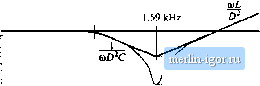 IZoll Z, [...........\S- = 7r- 100 H7 rig. 10.10 Construction of ] ZjvCW)) и and ]] Zj,jOw) !, buck converter example. transformer primary: (10.18) For the element values given in Fig. 10.8(a), this expression is equal to 4 Й. The Q-factor is given by = (10.19) This expression yields a numerical value Q = 3. The value of \ 7.{j{ii) at the resonant frequency 1.6 kHz is therefore equal to (4 Q)/{3) = 1.33 Q, At high frequency, H ZpOO)) II follows the retlected inductor asymptote. The quantity Z;(.v) is given by Eq. (10.7). This impedance is equal to the coitverter iitput impedance Z,-(j), uitder the coitditions that (.v) is varied to maintain the output voltage v{s) at zero. Figure 10.9(b) illustrates the derivation of an expression forZj). A testciirreut source is injected at the converter input port. The impedance Zs) can be viewed as the transfer function from (,jj,(j) Ю Рм(а) (10,20) The null condition \i,s) -0 greatly simplifies analysis ofthe circuit of Fig. 10,9(b). Since the voltage v(s) is zero, the currents tlirough the capacitor aud lo;id impedances are also zero. This further implies that the inductor current i) and transformer winding curreitts are zero, and hence the vuitage across the inductor is also zero. Finally, the voltage P,(j), equal to the output voltage plus the inductor voltage, is zero. Since the currents in the windings of the transformer model are zero, the current , /) is equal to the independent source current lA{iy. (10.21) Because Vj(,i) is equal to zero, the voltage applied to the secondary of the transformer model is equal to the independent source vuitage ~ V dis). Upon dividing by the turns ratio D. we obtain Pj.Cj): |