
|
| |
|
Строительный блокнот Introduction to electronics Fig. 10.11 Determitlation of llie filter output impedance ZJs).
V.vX*)=--p- [nsertjoii of b]S. (10.2!) and (10.22) into Eq. (10.20) leads to the following result: (10,22) (10.23) The steady-state relationship /=DV№has been used to simplify the above result. This equation coincides with the expression Usted tn Table 10.1. The Bode diagrain of 2д,(у(1)) is constructed in Fig. 10.10; this plot coincides with the dc asymptote of 2дОш). Next, let us construct the Bode diagram of the filter output intpedance When the independent source 0 is set to zero, the input filter network reduces to the circuit ofFig. 10.11. It can be seen that ZJs) is given by the parallel combination of the mductor and the capacitor Cj. (10.24) Construction of the Bode diagram of this parallel resonant circuit is discussed in Section 8.3.4. As illustrated in Fig. 10.12, the magnitude ZJjui) \\ is dominated by the inductor impedance at low frequency, and by the capacitor impedance at high frequency. The inductor and capacitor asymptotes intersect at the filter resonant frequency: Fig, 10.13 Magnitude plot of the output imped.rticc of the input Hiter of Fig, lO.11. Since the filter is not damped, die Q-fuctot is very large. 40 <ma 20 dBQ IQdDQ OdBH -tOdBft -гоава IZJf  100 Нг 40(1ВПт 30 dBQ 20 dBQ 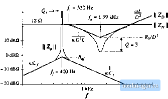 100 Нг LOkHz Fig. 10.13 Impedunce design criteria Z<a) sind ZC/ti)) from Fig. 10.10, wilh the filter ontput irapedaace il Z (/aj) II of Fig. 10.12 superimposed. The design criteria of Eq. (10.13) are not satisfied at the input filter resonance. (10.2.5) For the given values, the input filter resonimt frequency is j=40011z. This filter has characteristic impedance (10.26) equal to 0,84 Й. Since the input filter is undimiped, its factor is ideally infinite. In practice, piirasitic elements such as inductor loss and capacitor equivalent series resistance limit the value of 2/. Nonetheless, the impedance Zy(ycu) is vety hirge in the vicinity ofthe filter resonant fiequency./. The Bode plot of the filter output impedance ZJJixi) is overlaid on the 1 ZfJ(ii) [j and II Zp(j(t)) II plots in Fig. 10.13, for die element vaUie.s listed in Fig. 10.8(a). We can now determine whether the impedance inequalities (10.13) are satisfied. Note the design-oriented nature of Fig. 10.13: since analytical expressions ate given for each impedimce asymptote, the designer can easily adjust the component values to satisfy Eq. (10.13). Foreximiple, the values ofyaitd (should be chosen to ensure that the asymptotes ot \\ZJju>) \\ lie below the worst-ca.se value of R/D. ;is well as the other ;i.syniptotes It should also be apparent that it is a bad idea to chtxise the input and output filtei- resonant frequencies and jto be equal, because it would then be more difficult to satisfy the inequalities ofEq. (10.13). Instead, the resonant frequencies /о and .should be well separated in value. Since the input filter is undamped, it is impossible to satisfy the impedance inequalities (10.13) in the vicinity ofthe input filter resonant frequency У. Regardless ofthe choice of element values, the input filter changes the ctmtrol-to-output transfer function G ,j(.s) in the vicinity offrequency ff< Figures 10.14 and 10.15 illustrate the resulting correction factor [Eq. (10.12)] and the modified coutrol-to-output transfer function [Eq. (10.4)], respectively. At frequencies well below the input filterresonant frequency, impedance inequalities (10.13) are well satisfied. The correction factor tends to the value 1/0°, and the lOdB -lOdB 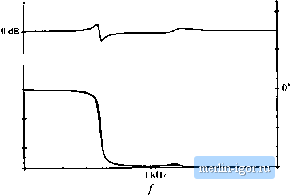 - leo- Z -360 1 +- 100 Hz [0 kill Fig, Ш.14 Miigniiiiilc or (ho correction factor, Щ. (10.12k fur the buck coiiveitcr example of Fig. lO.ii. 40(1B 30 dB 20 dB 10 dB OdB - 10 dB
100 Hz 1 Шг - ISO -360- -S40 lOkHi Fig. 10,15 Effect of the uiiduinped input filter on tha contnol-io-ouipiit transfer function of the buck converter example. Dashed lines: without input filtci. Solid tines: with tmdiitnped input (ilter. control-to-output transferfunction GJ,s) is essentially unchanged. In the vicinity of the resonant frequency/j, the correction factor contains a pair of complex poies, and also a pair of right half-plane complex zeroes. These cause a glitch in the magnitude plot of the correction factor, and they contribute 360° of lag to the phase of the correction factor. The glitch and its phase lag can be seen in the Bode plot of G ((.v). At high frequency, the correction factor tends to a value of approximately IZ- 360 consequently, the high-frequency magnitude of C/ is unchanged. However, when the - 360 contributed by the ctffrection factor is added to the - 180° contributed at high frequency by the two poles of the original G (i), a high-frequency phase asymptote of - 54t.f is obtained, If the crossover frequency of the converter feedback кюр is placed near to or greater than the input filter resonant frequency /j, then a negative |