
|
| |
|
Строительный блокнот Introduction to electronics phase margin is inevitable. This explains why addition of an input filter often leads to instabilities and oscillations in switching regulators. 10J.2 DampingthelnputFilter Lets damp the tesonance of the input filter, so that impedance inequalities (10.13) are satisfied at all frequencies. Otie approach to datnping the filter is to add resistor Jfm p;ir;diei with capacitor Cas illustrated in Fig. 10.16(a). The output impedance of this netwotk is identical to the parallel resonant impedance analyzed in Section 8.3.4. The maximum value of the output impedance occurs at the resonant frequency fj, and is equal in value to the resistance fij. Hence, to satisfy impedance inequalities (10.13), we should chtwse Kyto be much less than the {[ZfQiii) \\ and [[ZJijCi) \\ asytnptotes. The condition R-k \\ \\ can be expressed as: (10.27) Unfortunately, this raises a new problem: the power dissipation in /f.The dc itiput voltage V.. is applied across resistor R, and therefore ffy dissipates power equal to У/Нр Equation (10.27) implies that this power io s is greater than the load power! Therefore, the circuit of Fig. 10.16(a) is not a practical solution. One solution to the power loss problem is to place Rj in parallel with as illustrated in Fig. 10.16(b). Tlie value of ff, in Fig. 10.16(b) is ai.so chosen according to Eq. (10.27). Since the dc vohage across inductor is zero, there is now no dc power loss in resistor Ry. The problem with this circuit is that its transfer function contains a high-frequency zero. Addition of Rf degrades the siope of the high-frequency asyinptote. from - 40 dB/decade to - 20 dB/decade. The circuit of Fig. 10.16(b) is effectively a single-pole Д-Clow-pass filter, with no attenuation provided by inductori-r. One practical solution is illustrated in Fig. 10.17 [10]. Dc blocking capacitor is added in series with resistor Яу. Since no dc current can flow through resistor Д, its dc power loss is eliminated. The value of C(, is chosen to be very large such that, at the filter resonant frequency j, the impedance of the ffy-Cj branch is dominated by resistor R. When Cj is sufficiently large, then the output impedance of this network reduces to the output impedances ofthe filters of Fig. 10.1Й. The impedance asymptotes for the case of large Cj, are illustrated in Fig. 10.17(b). ТППГ ЛЛг- fig, W.m Two attempts to datnp the input filter: (a) addition of damping re.si.siiiiice Rj across Cy, (b) addition of damping resistance Win parallel with Lj-. о-nsvr 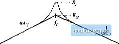 Fig. 10.17 A practical mcthotl to dampinj;; tlie input filter, iiicludiiie dnntping resistance вяпй dc blocking capacitor C,: (a) circirrt, (b) output impedance asympioies. 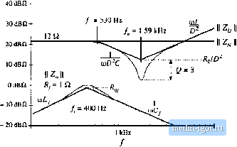 100 h7. lOkHi Fig. Ш,1Й Impedance design criteria ]] Z/d)) Ц and 2ц(/й) Ц Irom Fig. 10,10, with the iilier output impedance II Z (jcrj) II of Fig. 10.17(b) stiperimposed. The design criteria of Oq. (10.13) are well satisfied. The low-frequency asymptotes of f 2д-С/а)) and Z(jU) in Fig. 10.10 are equal to R/lfi= 12 ii. The choice = \ ii therefore satisfies impedance inequalities (10.13) very well. The choice Cj, = 4700 (tF leads to Шп/С = 0.084 Q, which is much smaller lhan Rj. The resulting magnitude II ZijiH) II is compared with [ Zijiil) \\ and Zo(jCU) in Fig. 10.18. It can be seen that the chosen values of/f,and lead to adequate damping, and impedance inequalities (10.13) are now well satisfied. Figure 10.19 illustrates how addition of the damped input filter modifies the magnitude and phase of the control-to-output transfer function. There is now very little change in G,.j,(s), and we would expect that the perforntance of the converter feedback loop is unaffected by the input filter. 10.4 DESIGN OF A DAMPED INPUT FILTER As illustrated by the example of the previous .section, design of an input filter require.s not only that the filter impedance asymptotes satisfy impedance inequalities, but also that the filter be adequately damped. Damping of the input filter is also necessary to prevent transients and disturbances in Vj(f) from exciting filter resonances. Other design constraints include attaining the desired filter attenuation, and minimizing 10.4 De.iigii of а Dampeil liipu! Fihei- 393 40 dB Fig. 10.19 Effect of the dmnped itiput niter on the contrtjl-to-uutput transfer function of the buck converter example. Danhed Шш: without input filter, Solid lines: witlt dumped input filter. 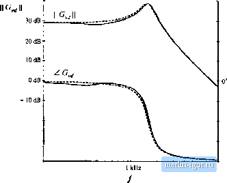 -ISO- 100Ш lOkHi the size of the reactive elements. Although a large number of classical filter design techniques are well known, these techniques do not address the problems of limiting the maximum output impedance and damping filter resonances. The value of the blocking capacitor Cj, used to damp the input filter in Section 10.3.2 is ten times larger than the value of C-, and hence its size and cost are of practical concern. Optimization of an input filter design therefore includes minimization of the size of the elements used in the damping networks. Several practical approaches to damping the single-section L-C low-pass filter are illustrated in Fig. 1020 [10.11,17]. Figure 10.2(Xa) cotitain.s die RfC, damping branch considered in the previous section. In Fig. 10.20(b>, the damping resistor fi-is placed in parallel with the filter inductor L, and a high-frequency blocking inductor L/, is placed in series with Ду. Inductor f-t, causes the filter transfer function to roll off with a high-frequency slope of - 40 dB/decade. In Fig. 10.20(c), the damping resistor -is placed in seties with the filter itiductor Lp and the dc current is bypassed by inductor Aj,. lu each case, it is desired to obtain a given amount of damping [i.e., to cause the peak value ofthe filter output impedance to be no greater than a given value that satisfies the impedance inequalities (10.13)], while minimizing the value of Q orL. This problem can be formulated in an alternate but equivalent form: for a given choice of C\ or f. tindthe value of Ry that minimizes the peak output impedance [10]. The solutions to this optimization problem, forthe three fiiternetworks of Fig. 21, are summarized in this section. In each case, the quantities /ijjandjare defined by Eqs. (10.25) and (10.26). Consider the filter of Fig. 10.20(b). with fixed values of LpCp and L. Figure 10.21 contains Bode plots ofthe filter output impedance ] Zfjti)) ] for several values of damping resistance R. For the limiting ca.se f= the circuit reduces to the original undamped filter with infinite Qj-ln the limiting case R= 0, the filter is also undamped, but the resonant frequency is increased because becotnes connected iu patidlei with Lp Between these two extremes, there must exist an optimutn value of f?y that causes the peak filter output impedance to be minimized. It can be shown [10,17] that ail magnitude plots must pass through acomnioit point, and therefore the optimum attains its peak at this point. This fact has been ti.sed to derive the design equations of optimally-datiiped L-C filter sections. |