
|
| |
|
Строительный блокнот Introduction to electronics © Fig, ]ft,20 .Stvtia) practical appmaclies lo dajiipiiij + (tie single-setliun input lilier: (a) Й-С paralid damping, (b) Rf-Lf patiiUel damping, (c) fi-ij, series damping. ТППР- ЛЛ/- 30 dB 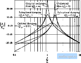 -30 dB Fig. 10.2] Coinparisoi! of output intpedatwc curves for Optiflia) paraiiol Rjlfj dainpitig with undamped and several suboptfinal designs. For this example, н = LJL - 0,5 IfJ II71 -ff 4ШЩ (10.30) The value of damping resistance thai leads to optimum damping is described by -/7 7 (10.31) 5l- ilMlM. V V 2n-(4 4- ) The above equations allow choice of the damping values and C,. For exatnple, lets redesign the dunping network of Section 10..3.2, to achieve the same peak Output impedance zOw) Ищщ ~ > while minimizing the value of the biockingcapacitance C . From Section 10.3.2. the other paiameier values are /tf,= 0,84 ii, Cy= 470 )i¥, and iy= 330 /iH, First, we solve Eq. (10.30) lo find the required value of n: (10,32) Evaluation of this expression with the given numerical values leads to n = 2.3. The blocking capaciloris therefore required to have a value of rtC = 1200 ftF. This is one-quarter ofthe value employed in Section 10.3.2. The value of is then found by evaluation ofEq. (10.31), leading to The output impedance of this filter design is compiired with the ouiput impedances ofthe original undamped filler of Section 10.3.1, and of the suboptimal design of Section 10.3.2, in Fig. 10.22. It can be 10.4.1 Ду-С Parallel Damping Optimization of (he filler neiwork ol Fig. \\).2{){ii) and Section 10.3.2 was described in [lOJ. The high-frequency aiienuation of ihis filter is noi affected by ihe choice of Cj, andthehigh-frequency asympioie vs idenlical lo lhai of the original undamped filter. The sole iradeolT in design ol the damping elemenls for this filler is in ihe size ofthe blocking capacitor Cj vs. ihe damping achieved. Forthis filler, let us define thequantity n as the ratio ofthe blocking capacitance lo ihe fiber capacitance C: = (10.28} For the optimum design, the peak fileeroueput impedance occurs at the frequency The value ofthe peak output impedance for the optimum design is tOdBil -10 dBQ - 20 ива -JOdBfl 100 Hi Undamped Suboptimal damping = 1 n 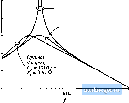 lO kHz Fig. 10.22 Comparison of lhe output impedances of the design with optima! parallel RfC), damping, the suhopti-mal design of Section 10.3,2, and ihe original undamped filter, seen that the optimally damped fdter does indeed achieve the desired peak output impedance of 1 Si, at the slightly lower peak frequency given by Et]. (10.29) The lij-Cij parallel damping approach finds significant application in dc-dc converters. Since a series resistor is placed in series with C; Cj, can be realized using capacitor types having substantial equivalent series resistance, such as electrolytic and tantalum types. However, in some applications, the approaches of the next subsections can lead to smaller designs. Also, the large blocking capacitor value may be undesirable in applications having an ac input. 10.4.2 /f-if, Parallel Damping Figure 10.20(b) illustrates the placement of damping resistor Kyin parallel with inductor fy. Inductor Lg causes the filter to exhibit a two-pole attenuation characteristic at high frequency. To allow Rto damp the filter, inductor L, should have an impedance magnitude that is sufficiently smaller than fiat the filter resonant frequency j. Optimization of this damping network is described in [17]. With this approach, inductur Lj, can be physically much smaller than L. Since R is typically much greater than the dc resistance of Lj-, essentially none of the dc current flows through Lj,. Furthermore, could be realized as the equivalent series resistance of ij at the filter resonant frequency f. Hence, this is a very simple, low-cost approach to damping the input filter. The disadvantage of this approach is the fact that the high-frequency attenuation uf the filter is degraded: the high-frequency asymptote of the filter transfer function is increased from l/tuLy to ]f(ii\L\\Li)Cj: Furthermore, since the need for damping limits the maximum value of ij significantioss of high-frequency attenuation is unavoidable. To compensate, the value of must be increased. Therefore, a tradeoff occurs between damping and degradation of high-frequency attenuation, as illustrated in Fig. 10.23. For example, limiting the degradation of high-frequency attenuation to 6 dB leads to an optimum peak filter output impedance of Jb times the original characteristic impedance Л,, Additional damping ieads to further degradation of the high-frequency attenuation. The optimally damped design (i.e., the choice of Яу that minimizes the peak output impedance |