 | |
|
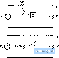
Строительный блокнот Introduction to electronics ues of the waveforms can be determined by simply equating the average source and load powers. The average power tlttwlng intt) the converter input port is p .Yl CI 1-29) where P is the average pttwerconsiimed hy the effective resistance R. No average power is consumed by capacitor C, and hence the average power ratistflowentirely into the load resistor/i: p (11.30) Upon equating Eqs. (11.29) and (11.30), we obtain Thus, the rms terminal voltages obey the same relationship as in the dc case. Averaged eqtiivalent circuits of the ЕЮМ buck, bottst, and buck-boost converters, as well as the DCM Cuk and SEPIC converters, are listed in Fig. 11.11. In each case, the averaged transistor waveforms obey Ohms law, and are modeled by an effective resistance R,., The averaged diode waveforms follow a power source characteristic, equal to the power effectively dissipated in /f,.. For the buck, boost, and buck-boost converters, R is given by For the Cuk and SEPIC converters, R, is given by .2(L,lf ) (illaj (11.33) Here, d is the transistor duty cycle. Steady-state conditions in the converters of Fig. 11.11 are found by letting the inductors and capacitors become short-circuits and open-circuits, respectively, and then solving the resulting dc circuits with J(f) = D. The buck-boost, Cuk, and SEPIC then reduce to the circuit of Fig. 11.9. The buck and boost ctmveiters reduce to the circuits of Fig. 11.12. Equilibrium conversion ratios И = V/V of these converters are summarized in Table 11.1, as functions of R.(D). It can be shown that these converters operate in the discontinuous conduction mode whenever the load current / is less than the critical current 1>! for CCM -13ф, l<l f, for DCM For all of these converters, Z.,-, is given by D RAD) I I.I DCM .Averaged Switch M/tdel 419 Buck Boon Buck-boosl (MO), Ф 1 r ft (< )г, Cttk ТПЛГ SEPIC 4 ► Fig, 11.11 Averaged large-signal equivalent circuits ot live basic conveners operating in tlje discontinuous con-d net lot) mode.  Flft 11.12 Dc equivalent clrcuiis representing [he buck (a) and boost (b) conveners operating in DCM, Till)le 11.1 CCM and DCM eunversion rutios of basic conveiters
11.2 SIVIALL-SKINAL AC IVIODELlNt; OF THE DCM SWITCH NETWORK Tlie next step is construction of a small-signal etuivalent circuit motiel for converters operating in the discontinuous conduction mode. In the large-signal ac equivalent circuits of Fig. 11.11, the averaged switch networks are nonlinear. Hence, construction of a small-signal ac model involves perturbation and linearization of the loss-free resistor network. The signals in the large-signal averaged DCM switch network model of Fig. 11.13(a) are perturbed about a quiescent operating point, its follows: |