 | |
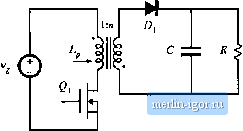
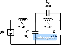
Строительный блокнот Introduction to electronics  Mg, 11,23 Flybackcntiveiter, Ftoblem 11.1. Fig. 11.24 Watkinft-Johnsoncoiiverrer, Problem 11,2, (c) Solve your moJel lo delermine the converter conversion raiio M(D) - V/V in the discontintious condticiion mode. Over what range of load currents is your expression valid? 11.3 Skelch lhe sleady-slate output characlerislics of lhe buck-boo.sl converter: plot the oulpui vollage V vs. the Itjad currenl /, for seventl valties of duly cycle D. Include bolh CCM and DCM operulion, and clearly label the bimndiiry belween raode.s. 11.4 In the network of Fig. II,25, the power sotirce waveform ;)(r) is given by p{i)= 1000 ciw 377r The circtiit opentles in steady stale. Determine the rms resisUjr voltage jj- 11.5 Verify the expressions for G,j(5 and uj, given in Table 11.3. 11.6 A certain buck converter operates with an inpul vollage of V, = 2K V and an otitput voltage of V= 15 V. The loiid resi.slance i.s R =1012. Otltcr element and parameter values are: L = КцН, С = 220R Д= 150кН/, (a) Determine the value of K. (b) Determine die quiescent duty cycle D. (c) Skelch a Bode plot of lhe conlrol-to-oulpul transferfunction f j(-v). Label lhe values of all salient feaUiies. You may neglect inductor dynamics. 11.7 Using the approach of Section 11.3, determine the c<mtrol-lo-output transfer function C,(s) of a boost converter. Do nol make lhe approximation Ls= 0, Problems  Fig. 11,25 Network with a power source, Ptcblem 11,4, (a) Derive atialylical expressions for the dc gain an J (he RHP zero frequency lo, as functitms of M, R, D, Vj i, C, Eintl Л, (b) With the assumption that С is sufficiently large and that L is sufficiently small, the poles of G{s) can be factored usini; the кш-Q approximation. Do so, and express the two poles as funttions of jW, D, L, C, and Л. Show that the low-fretjuency pole matches the expression in Table 11.3, and that the high-fretjuency pole is given by the expression in Table 11,4. This page intentionally left blank |