
|
| |
|
Строительный блокнот Introduction to electronics Fib. 12.3 Inductor cutrcnt waveform t)f jl current-piogramnned convcrtet operating in tlie continuous conduction mode.  the artificial ramp are explained, using a simple first-order discrete-time analysis. Effects of the artificial ramp on controller noise susceptibility is also discussed. Figure 12.3 illustrates a generic inductor current waveform of a switching converter operating ill the continuous conduction mode. The inductor cnrrciit changes with a slope during the first sub-interval, and a slope -m during the second subintcrvai. For the basic nonisolated converters, the slopes m, and - Ш, are given by in I = - ,- - illj = - Buck converter L Boost converter Buck-boost converter (12.1) With knowledge of the slopes jHj and -m, we can dctcrniinc the general relationships between 1(0), t, (,.(7;), and dT. During the first subinterval, the inductorcurrent l(() increases with slope Ш[,until reaches the control signal Hence, (12,2) Solution for the duty cycle d leads to (12.3) 111 a similar manner, for the second subinterval we can write (12,4) In steady-state, ;(0) = г(Г,), d-D,ii}f - M and =Mj, Insertion of these relationships into Eq. (12.4) yields Fig. 12.4 Effect of itihisl pejtur-batioti tJP) on inductor current waveform. state 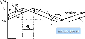 -m, .i-Perturbed wavefortn {D + d]T DT. 0 = MDT,-MiiyT, (12.6) Steady-State Eq. (12.6) coincides with the requirement for steady-state volt-second balance on the inductor. Consider now a small perturbation in ijiQ). i,(O) = /, + i,(0) (12.7) 7((, is a steady-state value of /(0), which satisfies Eqs. (12.4) and (12.5), while (, (<)) is a small perturbation such that m\-\h. (12.8) It is desired to assess the stability of the current-programmed controller, by determining whether this small perturbation eventually decays to zero. To do so, let us solve for the perturbation after n switching periods, ti<iiiTJ), aitd detemiine whether ttinTJ), tends to zero for large n. The steady-state and perturbed inductorcurrent waveforms are illustrated in Fig. 12.4. For clarity, the size ofthe inductor current perturbation 1 (0> is exaggerated. It is assumed that the converter operates near steady-state, such that the slopes rn and /Hj are essentially unchanged. Figure 12.4 is drawn for a positive Г(О); the quimtity dT is then negative. Since the slopes ofthe steady-state and perturbed waveforms are essentially equal over the interval (i < J < (D + t})T, the difference between the waveforms is equal to (,( forthis entire interval. Likewise, the difference between the two waveforms is a constant i(,TJ over the interval (D + d)T < r < Г, since both waveforms then have the slope ~ ffij, Note that tjiT) is a negative quantity, as sketched in Fig. 12.4. Hence, we can solve for liT) in terms of Г,.(0), by considering only theinterval {D + J)!] < t < ОТ, as illustrated in Fig. 12.5. Fig, 12,5 Expattded view of the steady-state and perturbed inductor current waveforms, neur the peak afij:t}. 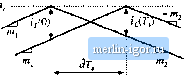 Steady-state waveform Perturbed waveform From Fig. 12.5, we can use tlie steady-state waveform to express г7(0) as the slope multiplied by the interval length - T. Hence, (12.9) Likewise, we can use the perturbed waveform to expiess t,/? ,) as the slope - ittj, multiplied by the interval length - ill;. Elimination of the intermediate variable d from Eqs. (12.9) and (12.10) leads to ,(r,) = tV(0) ffl; ft I (12.10) (12.11) If the converter operating point is sufficiently close to the quiescent operating point, then ffVl given approximately by Eq. (12.6). Equation (12.11) then becomes A similar analysis can be performed during the next switching period, to show that r,(27,) = r (7,)--g]=, j-] After switching periods, the perturbation becomes .( T,) = ?,f(/i~ 1)7;,) = ?,(0) (12.12) (12.13) (12,14) Note that, as ;/ tends to infinity, the perturbation tjiiT,) tends to zero provided that the characteristic value ~ DJD has magnitude less than one. Conversely, the perturbation irtT) becomes large in magnitude when the characteristic value a - -DID has magnitude greater than one:
(12.15) Therefore, for stable operation of the current programmed controller, we need I a = D/D < 1, or /J<0.5 (12.16) As an example, consider the operation of the boost converter with the steady-state terininal voltages = 20 V, V = 50 V. Since V/V = l/D, the boost converter should operate with D = 0.6. We therefore expect the current programmed controller to be unstable. The characteristic value will be |