
|
| |
Строительный блокнот Introduction to electronics 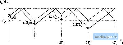 О 7, Fig. U.6 Unstable oscillation for D = 0.6. (R17) As given by Eq. (12.14), a perturbation in the inductorcurrent will increase by a factor of- 1.5 over every switching period. As illustrated in Fig. 12.6, the perturbation grows to - 1.5г(0) after oite switching period, to + 2.2S?j(0) after two switching peiiods, and to - 3.375Г;(0) after three switching peiitxls. For the particular initial conditions illustrated in Fig. 12.6, this growing oscillation saturates the current programmed controller after three switching periods. The transistor remains on for the entire duration of the fourth switching period. The inductor current and controller waveforms may eventually become oscillatory and periodic in nature, with period equal to an integral ntmiher of switching periods. Alternatively, the waveforms may become chaotic. In either event, the controller does not operate ns intended. Figure 12.7 illustrates the inductorcurrent waveforms when the output voltage is decreased to V = 30 V. The boost converter then operates with D = 1/3, and the characteristic value becomes (12.18) Perturbations now decrease in magnitude by a factor of 0.5 over each switching period. A disturbance in the inductor current f}ecomes sirtail iit magnitude after a few switching periods. The instability for D > 0.5 is a well-known problem of curreiu programmed control, which is not dependent on the converter topology. The controller can be rendered stable for ail duty cycles by addition of an artificial rainp to the sensed switch current waveform, as illustrated in Fig. 12.8. This arti-  0 T, Fig, 12,7 A stable transient with D - 1/3. 37 . Buck converter .-.(0 Measure hit) switch currenl Control input Artificial ramp
comparator Latch Current-programmed controller 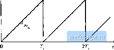 Fig. 11.8 Stabilization of the current progranuued controller by Luldition of an artilicLul tamp to the measured switch current waveforar: (a) block diagrain, (b) artificial ramp waveform. ficial ramp has the qualitative effect of reducing the gain of the inner switch-current-sensing discrete feedback loop. The artificial ramp has slope m as shown. The controller now switches the transistor off when i (dT,) + i, [dT,)i, (12.19) where ( (f) is the artificial ramp waveform. Therefore, the transistor is switched off when the inductor current yf) is given by t,.{,) = i,-t (Jr.) (12.20) Figure 12.9 illustrates the analoi; comparison of the inductor current waveform 1(0 with the quantitv Fig, 12,9 Addition of artificial ramp: the transistor is now switched off wlien 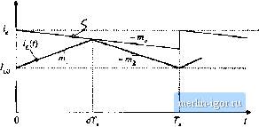 We can again determine the stability of the current programmed controller by analyzing the change in a perturbation of the indnctor current waveform over a complete switching period. Figure 12.10 illustrates steady-state and perturbed inductor current waveforms, in the presence of the artificial ramp. Again, the inagnitude of the perturbation 1*(0) is exaggerated. The perturbed waveform is sketched fora positive value of/,(0); this causes d, and usually also to be negative. If the perturbed wave- forms are sufficiently close to the quiescent operating point, then the slopes fflj and 1Щ are essentially unchanged, and the relationship between rj(0)and (ДТ)сап be determined solely by consideration ofthe interval (D 4 d)T < t < DT... The perturbations ((0) and ,.(7 ) are expressed in terms of the slopes fflj, ra, andm , and theinterval length-/jT as follows: r,fO)=-T.(m,+m,) (12.21) Elimination of yields ?J/;) = --rfr,(m -tnj) (12.22) A similar analysis can be applied to the и* switching period, leading to №) = fit(,!--l)7;) !nizf!h\-t, .(0) = i,(U)a (12.23) (12.24) The evolution of inducttir cunent perturbations are now determined by the characteristic value Fig. 12.ie Steady-state and perturbed induclor current waveforms, in the presence of an artificial ramp. zo +
|
|||||||||||||||||||||||||