
|
| |
|
Строительный блокнот Introduction to electronics S.2 Inclusion of Inductor Copper Loss 43 ЛЛг- 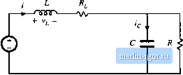 Fig. 3,7 Boost convener circuits during the two subiiitervals, iticluding inductor copper Irws resistance R\ (a) with the switch in position I, (b) with the switch in position 3. become t3.8) РогОГ, <t< 4\, the switch is in position 2 and the circuit reduces to Fig. 3.7(b). The inductor current and capacitor voltage are then given by (3.9) We again make the small-ripple approximation. The principle of inductor volt-second balance can now be invoked. Eijnations (3.8) and (3.9) aie used to construct the inductor voltage waveform vjt) in Fig. 3.8. The dc cotnponent, or average value, of the inductor voltage vjf) is By setting (v, ) to zero and collecting terms, tme t)btains 0=V -FR-DV (3,10) 0.11) (recall that D + D - 1). It can be .seen that the inductor winding resi.stance R, adds another term to the inductor volt-second balance eqtiation, In the ideal boost converter (Л = 0) example of Chapter 2, we were able to solve this equation directly ft)r the voltage conversion ratlt) VW,.Equation (3.11) cannot be immediately solved in this manner, because the inductor current / is unknown. A second equation is needed, to eliminate /. 4(f) Fig. 3.8 Inductcr voltaec and capaoitor ciiireiit waveforms, for the noiiideal boost converter of Fig. 3.6. V. -IR,
The second equation is obtained using capacitor charge balance. The capacittff current waveform is given in Fig. 3.8. The dc component, or average value, of the capacitor current waveform is (3.12) By setting (i} to zero and collecting terms, one obtain.s 0 = D/- (3,13) We now have two equations, Eq.s. (3.11) and (3.13), and two imknowns, V and 1. Elimination of / and solution for F yields H - L (3.14) This is the desired solution for the converter output voltage V. It is plotted in Fig. 3.9 for several vahies of RJR. It can be seen that Ec]. (3.14) contains two terms. The first, \ У, is the ideal conversion ratio, with R, = 0, The second term, describes the effect of the inductor winding resistance. If/f;,is much less than DR, then the second term is approximately equal to unity and the conversion ratio is approximately equal to the ideal value l/D. However, as R\.4 increased in relation to DR, then the .second term is reduced in value, and V/V is reduced as well. As the duty cycle D approaches one, the inductor winding resistance/?!, causes a major qualitative change in the V/V curve. Rather than approaching infinity at D= I, the curve tends to zero. Of course, it is unreasonable to expect that the converter can produce infinite voltage, and it should be comforting to the engineer that the prediction of the model is now more realistic. What happens at D = 1 is that the switch is always in position I. The inductor is never connected to the output, so no energy is tran.sferred to the output and the output voltage tends to zero. The inductor current tends to a large value, limited only by the inductor resistance A large amount of power is lost in the inductor winding resistance, equal to V/R, while no power is delivered to the load; hence, we can expect that the converter efficiency tetids to zero at D = 1. Another implication of Fig. 3.9 is that the inductor winding resistance R limits the maximum 3J Cnnsiruaion of Equivalem Circuii Model 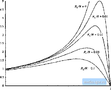 0 0.1 0.2 0.3 0.4 0.5 0-6 0.7 0.8 0.9 Fig, 3.9 Oi]tput voltage vs. duty cycle, boost converter with InsJucior topper loss. voltage that the converter can produce. For example, with R[/R - 0,02, it can be seen that the tnaxiramn V/Vj is approxitnately 3.5. Hit is desired toobtain VIV = 5,the.n according to Fig. 3.9 the inductor winding resistance must be reduced to less than l%of the load resistance R. The only problem is that decreasing the inductor winding resistance requires building a larger, heavier, more expensive inductor. So it is usually important to optimize the design, by correctly modeling the effects of loss elements such as and choosing the smallest inductor that will do the job. We now have the analytical ttmls needed to do this. CONSTRUCTION OF EQUIVALENT CIRCUIT MODEL Next, let us refine the dc transformer model, to account for converter losses. This will allow ns to determine the converter voltages, currents, and efficiency using well-known techniques of circuit ;tnalysis. In the previotis section, we tised the principles of inductor volt-second balance and capacitor charge balance to write Eqs. (3.11) and (3.13), repeated here: {v,}=o=v-iR,-av (3.15) These equations state that the dc components of the inductor voltage and capacitor current are equal to zero. Rather than algebraically staving the equations as in the previous section, we can reconstruct a circuit mt)del based on these equatit)ns, which describes the dc behavior of the bot)st converter with inductor copper loss. This is done by constructing a circuit whose Kirchoff loop and nt)de equations are |