
|
| |
|
Строительный блокнот Introduction to electronics <b) 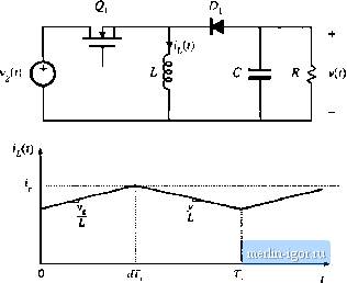 Fig. 12.13 ВиЛ-boost tonvcrter example: (a) power stage, (b) iiiduetor current waveform. (12.31) We now make the assunaption that the intluctor current \j{.<t) is identical to the programmeil control current This is valii] to the extent that the controller is stable, anil that the magnituiles of the inductor cunent ripple aud artificial ramp waveform are sufficiently smiill: (12,32) This approximation, in conjunction with the inductorcurrent equation of (12.31), can now be used to find the relationship between the control current ijs) and the duty cycle 3{s), as follows: .!fj*,(.v) = D(!(i) -t- Dlis) + \V- Vy(s) Solution for d{s) yields r/CO = jLi,(j)-DC,(-tJv(.r) (12.33) (12,34) This small-signal expression describes how the current programmed controller varies the duty cycle, in response to a given control input variation \is)- It can be seen that d{s) depends not only on tj.s), but also on the converter output voltage and input voltage variations. Equation (12.34) can noW be substituted into the sectmd and third lines of Eq. (12.31), thereby eliminating d(s). One obtains 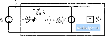 Node С 5 я Fljs. 12,14 Coiwitruction of CPM CCM buck-boosi converter equivalettt circuit; (a) ttiput port model, corresponding to Eq. (12.38); (b) output port model, corresponding to Oq. (12.37). .cv(.)=..D-;.(.)-Mw/-->- ->- - (12.35) These equations can be simplified by collecting terms, and by use of the steady-state relationships - DR DR > Equation (12.35) then becomes (12,36) .vCv(.v) = sLD DR
4s] - (12.37) (12.38) These are the basic ac small-signal equations for the simplified frrst-order model of the current-programmed buck-boost converter. These equations can now be used to construct small-signal ac circuit triodeis that represent the behavior of the converter input and output ports. In Eq. (12.37), the quantity aCvis] is the output capacitor current. The ijis) term is represented in Fig. 12.14(b) by an independent Fig. 12.15 Two-port equivatent circuit used lo tnodet the current-proEratntned CCM buck, boost, and buck-boost converters. current source, while the ((i) term is represented by a dependent current source. v(s)tR is the current through the load resistor, and v(i)D/fl is the current through an effective ac resistor of value R/D. Equation (12.38) describes the current i(s) drawn by the converter input port, out ofthe source Vjfis). The i(s) term is again represented in Fig. 12.14(a) by an iirdependent cunent source, and the v(.f) term is represented by a dependent current source. The quantity - vis)D/DR is modeled by an effective ac resistor having the negative value - DRID. Figures 12.14(a) and (b) can now be combined into the smali-signal two-port mtxiel of Fig. 12.15. The current programmed buclt and boost converters can also be modeled by a two-port equivalent circuit, ofthe same form. Table 12.1 lists the model parameters for the basic buck, btrast, and buclt-boost converters. The two-port equivalent circuit can now be solved, to find the convertertransfer fimctions and output impedance. The control-to-output transfer function is found by setting to zero. Solution for tlie output voltage then leads to the transfer function G(s): G .(.0= lis) (12,39) Substitution ofthe model parameters for the buck-boost converter yields -Sk 1 +[> (12,40) Tlible 12,1 Current proramtned mode sinall-signal equivalent cirtuit parameters, simple inodel Converter Buck Boost Buck-boost £ l + sL Ш sDL DR |