
|
| |
|
Строительный блокнот Introduction to electronics 6 mi-T ТППГ \ Switch network small-signal ac ttxodel \ Fig, t3.19 Small-signal tm>de] of tlit; CCM c buck converter, derived by petturbation and linearization (if the switch network in Fig. 1Э.17. Soiiititm for the smali-signai switch network input current IlCO yields The small-signal ac model of Fig. 12.1У can now be constructed. The switch network output port is again a current source, of value ijj). The switch iietworlt input port model is obtained by linearization of the power sink characteristic, as given by Eq. (12.53). The input port current l*(f) is compo.sed of three terms. The ((r) term is modeled by an independent current source, the VjCO term is mtxleled by a dependent current source, and the Vj(() term is modeled by an effective ac resistor having the negative value - Уll\ .\\ illustrated in Fig. 12.20, diis incremental resistance is determined by die slope ofthe power sink input port characteristic, evaluated at the quiescent operating point. The power sink leads to a negative incremental resistance l)ecause an increase in (VjCf)),. causes a decrease in {/((/)such that constant {p(t)),; is maintained. The equivalent circuit of Fig. 12.19 can now be simplified by use of the dc relations VDV, i.j = VJR, /, = ZJ/j, l = Equation (12.53) then l)ecomes (12.52) (12.53)
Fig. 12,20 Origin of the input port negative incneraentai resistance Vy liic slope of the power sink charaeteristio, evaluated at die quiescent operating point. *,(f) = Di + 4f)-i5,(t) (12,54) Finally, wecan eliminate thequantities V( and it favor of the converter terminal voltages and as follows. The quantity is simply equal to iJ. Thequantity Oj is equal to the output voltage \> plus the voltage across the inductor, slJis). Hence, .6 6 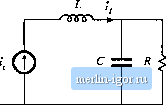 fig. 12.Z1 Simplificaiion of the CPM buck converter model of Fig. 12.19, with dependent source expressed in terms uf the output voltage vLiriaiionS. With these snbstitutions, Eq. (12.54) becomes (12.55) r,(i) - О [ 1 + s ) (\(j) +1 vis)- (12.56) The equivalent circtiit of Fig. 12.21 is now obtained. It can be verified that this equivalent circuit coincides with the model of Fig. 12.15 and the buck converter parameters ofTable 12.1. The approximate small-signal properties of the current programmed buck converter can now be explained. Since the inductor is in series with the current sotirce i, the indtictor does not contribute to the control-to-output transfer function. The control-to-output transfer ftinction is determined simply by the relation (12.57) So current programming transforms the output characteristic of the buck converter into a current source. The power sink input characteristic of the current programmed buck converter leads to a negative incremental input resistance, as desciibed above. Finally, Fig. 12.21 predicts that the btick converter line-to-otitput transfer function is zero: (12,58) Disturbances in do not influence the output voltage, since the inductor ctirrent depends only on i. The current programmed controller adjusts the duty cycle as necessary to maintain constant inductorcurrent, regardless of variations in v, The more accurate mixiels of Section 12.3 predict that GC) is not zero, but is nonetheless small in magnitude. Similar arguments lead to the boost converter small-signal equivalent circuit of Fig. 12.22. Derivation of this equivalent circuit is left as a homework problem. In the case of the boost converter, the switch network input port behaves as a current source, of value j, while the output port is a dependent power source, equal to the power apparently consumed by the current source i. In the small-signal model, the current source appears in series with the inductor L, and hence the converter transfer functions cannot contain poles arising from the inductor. The switch network power source output characteristic leads to an ac resistance ofvalue = R, The llne-to-oiitptit transfer ftinction is nonzero in the 6 Ф Pig. 12.22 Sinall-signal model uftlie CCM CPM boost converter, derived via averaged switch modeling and the approximation = j. bot)st converter, since the magnitude of the power source depends directly on the value of v. The control-to-output transfer function contains a right half-plane zero, identical to the right half-plane zero of the duty-cycle-controlled boost converter. 12,3 A MORE ACCURATE MODEL The simple models discussed in the previous section yield much insight into the low-frequency behavior of current-prograraraed converters. Unfortunately, they do not always describe everything that we need tt) know. For example, the simple m[)dei [)f the buck converter predicts that the line-t[)-output transfer function Gj.(j) is zero. While it is true that this transfer function is usually small in inagnitude, the transfer function is not equal to zero. To predict the effect of input voltage disturbances on the output voltage, we need to compute the actual <J,/-f}- In this section, a more accurate analysis is performed which does not rely on the approximation (/.())г ~ tffS). The analytical approach of [5,6] is combined with the controller model of [7]. A functional block diagram of the current programmed controller is constructed, which accounts for the presence of the artificial ramp and for the inductor current ripple. This block diagram is appended to the averaged converter models derived in Chapter 7, leading to a complete conveiter CPM model. Models for the CPM buck, btmst, and buck-boost converters are listed, and the buck converter model is analyzed in detail. 12.3,1 Current Prugrammed Controller Model Ratherthan using the approximation {(; (f)) = {t(/))j., let us derive a more accurate expression relating the average inductor current (fi(O)j-j to he control input tit). The inductor current waveform is illus-U-ated in Fig. 12.23. It can be seen tliat the peak value of r,(/) differs from ljd\ by the magnitude of the artificial ramp waveform at time / = dT that is, by w rfT. The peak and average values of the inductor current waveform differ by the average value of the inductor current ripple. Under transient conditions, in which if(0) is not equal to tlCQ, the magnitudes of the inductor current ripples during the di\ and dtl subintervals tue mdTJI and fKjjrespectively. Hence, the average value of the inductor current ripple is d[mdrj2) + ft(mTJ2). We can express the average inductor current as II. s dt T (12.59) |
||||||||||||||