 | |
|
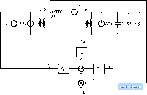
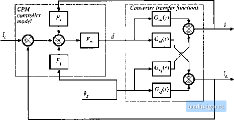
Строительный блокнот Introduction to electronics m Boost  (c) Buck-boost  Fig. 11.25 Continued.  Fig. 12.16 Block diagram that models the current-programmed converters of Fig, 12.25. r 1Л - i-i U2.69) Figure 12.26 illustrates replacement of the converter circuit m[>deis of Fig. 12.25 with block diagrams that cotresptuid to Eqs. (12.67) and (12.68). The control-to-output and line-to-output transfer functions tan now be found, by manipulation of the block diagram of Fig. 12.26, or by algebraic elimination of (/and r, from Eqs. (12.66), (12.67), and (12.68), and solution for v. Substitution ofEq. (12.68) iitto Eq. (12.66) and solution for j leads to By substituting this expression into Eq. (12.67), one obtains (l+FG ) I Solutioit of this equatioit for v5 leads to the desired result: (12,70) (12.71) Therefore, the current-prograinined control-to-output transfer ftinction is (12.72) The turrent-programmed liiie-to-witpiit tnmsfer function is --- C12-?3) (12.74) Equations (12.73) and (12.74) are general expressions for the important transfer functions of singie-indtic tor current-programmed converters operating in the continuous conduction mode. 12.3.3 Discussion The controller inodel ofEq. (12.Й6) and Fig. 12.24 accounts for the differeitces between and that arise by two mechanisms: the inductorcurrent ripple and the artificial ramp. The inductorcurrent ripple causes the peak and average values ofthe inductor current to differ; this leads to a deviation between the average inductor current and i. Since the magnittide of the inductor current ripple is a function of the converter input and capacitor voltages, this mechanism introduces v, and v dependencies into the contrt)i-ler smaii-signai block diagram. Thus, the and gain bKx;ks of Fig. 12.24 model the small-signal effects of the inductor current ripple. For operation deep in continuous conduction imxle {lURT э> 1), the inductor current ripple is small. The and F, gain bloclcs can then be ignored, and the inductor current ripple has negligible effect on the current programmed controller gain. The artificial ramp ai.so causes the average inductorcurrent to differ from t. This is mtxleled by the gain bkxk F, , which depends inversely on the artificial ramp slope M. With no artificial ramp, Л/ = 0 and tends to infinity. The current-programmed control systems of Fig. 12.25 then effectively have infinite loop gain. Since the duty cycle is finite, the signal at the input to the F, bkx;l<; (£&f, ) must tend to zero. The bloclc diagram then predicts that f = 0 = -b.-FA-F.S (12.75) In the case of negligible indiictorcurrentrippie {F - * 0 and F -* 0), this equation further reduces to 0 = f,-,\ (12.76) This coincides with the simple approximation employed in Sectitm 12.2. Hence, the transfer functions predicted in this sectitm reduce to the results [)f Sectitm 12.2 when there is no artificial ramp tuid negligible inductor current ripple. In the limit when F, F 0, and F -* 0, the controi-to-output transfer function (12.73) reduces to lim Ga.) = (12.77) and the iine-tti-output transfer functitm reduces to |