
|
| |
|
Строительный блокнот Introduction to electronics 40 dB IIG I!  -180* to Hz 100 Шг Fig. 12.27 Comparison of CPM contml wilh diUy-cjicle control, for die eontrol-lo-output fnequency resjxinse of the buck convener example. lie, vg I 20 dB -20 dB -40 dB -60 dB -SOdB -ICOdB Duty cycle control d{t) = constant  Ctirrent programmed tnode vp) = constant to Hz 100 Uz 1 kHz 10 kHz 100 kHz Fig. 12.28 Comparison of CPM control with diriy-cycle comrol, foi tlie line-to-output freqttency response of the buck converter example. having ample phase margin over a wide range of operating points. Proportional-plus-integral (Pfl controllers are commonly used in current-programmed regulators. The line-to-output transfer functions of the same example are tompiued in Fig. ]2.2S. The line-to-output transfer function G(.t) for duty-cycle control is characterized by a dc asymptote approximately e(]u;i] to the duty cycle D ~ 0.676. Resonant poles occur at the comer frequency of the L-C filter. The line-to-output transfer function G,i.J,Si) with current-programmed control is .significantly reduced, and exhibits more than 30 dB of additional attenuation over the frequencies of interest. It should again be 20 dBQ l!Z JI OdBffl -20 dun Current programmed mode vJX) - constant Duty cycle control d{t) = constant  10 Hz 100 Hz i kHz 10 k№ 100 kHz Fif. 12.29 example. Compaiisoii of CPM ccmtiol with duiy-cycle cuatiol, fur [lie outpul ijupedantc of the buck converter noted that the transfer function trj, ,(1) in Fig. 12.2E cannot be predicted by the simple models of Section 12.2; the more accurate model of Section 12.3 must be employed. The effect of current-programmed control on the converter output impedance is illustrated in Fig. 12.29. The output impedance plotted in the figure includes the load resistance of 10 S2. For duty-cycle control, the dc asymptote of the output impedance is dominated by the inductor winding resistance of 0.05 Q. The inductor becomes significant in the vicinity of 2ffl) Hz. Above the resonant frequency of the output filter, the output impedance is dominated by the output filter capacitor. For current-programmed control, the simple model of Section 12.2 predicts that the inductor branch ofthe circuit is driven by a current source; this effectively removes the influence ofthe inductor on the output impedance. The plot of Fig. 12.29 was generated using the more accurate model of this section; nonetheless, the output impedance is accurately predicted by the simple model. The dc asymptote is dominated by the load resistance, and the high-frequency asymptote follows the impedance of the output fiUer capacitor. It can be seen that current programming substantially increases the converteroutput impedance. 12.4 DISCONTINUOUS CONDUCTION MODE Current-programmed converters operating in the discontinuous conduction mode can be described using the averaged switch modeling approaches of Sections 12.3 and 11.1. It is found in this section that the average transistor voltage and current follow a power sink characteristic, while the average ditide voltage and current obey a power source characteristic. Perturbation and linearization of these characteristics leads to a small-signal equivalent circuit that models CPM DCM converters. The basic DCM CPM buck, botwt, and buck-boost converters essentially exhibit singie-poie transfer functions: the second pole and the right half-plane zero appear at frequencies near to or greater than the switching frequency, owing to the small value ofL in DCM. A DCM CPM buck-boost converter exatnple i.s analyzed here. However, Eqs. (12.103) to (12.120) are written in general form, and apply equally well to DCM CPM buck and boost Converters. The schematic of a buck-boost converter is illustrated in Fig. 12.30. The terminal waveforms of the switch network are defined as shown: and i{t) are the transistor waveforms, while i.j(/) and jj(() are Switch network Fig. 12.30 Cuireru-programmed DCM buck-boo$t converter example. 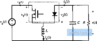 the diode waveform.s. Figirre 12.31 illustrates typical DCM waveforms, for current-programmed control with an artificial ramp having .slope - m,. The inductor current is zero at the beginning of each switching period. By .solution of the transistor conduction subinterval, the programmed current г can be related to the transistor duty cycle by: = (tn,. Solution for [J, leads to (12.103) (12.104) The average transistor current is found by integrating the i,(t) waveform of Fig. 12.31 over one .switching period: (12.105) The total area / is equal to one-half of the peak current ij,, multiplied by the subinterval length dT, Hence, (<,(rt),4t (r)J,(0 П2.Ю6) Elimination of г, and d, to express the average transistor current as a function of (., leads to (12.107) Finally, Eq. (12.107) can be rearranged to ohtain the averaged switch network input port relationship: (12.108) 1 +- |