
|
| |
|
Строительный блокнот Introduction to electronics An artificial rump is enoployeJ, tiaving slope 0.15 A/fiSec. (aJ Construct tlic magnitude and phase asymptotes of the control-to-output uansfer function C,x) for duty-cycle control. On the same plot, construct the magnitude iind phase asympiotes of the control-to-output tran.sfer function C.W for cLirrenl-programmed control. Compare. (b) Construct the magnitude asymptotes of the line-to-output transfer function .(j) forduty-cycle control. On the same plot, constmct the magnitude asymptotes of lhe line-to-output transfer function G j. (j) for current-programmed control. Compare. 118 A buck-boost converter operates in lhe discontinuous conducliun mode. Its current-programmed control- ler has no compensating artificial ramp: i = 0. (a) Derive an expression for the conlrol-lo-oulput transferfunction Gj.(s), using the approximation !, = 0. Give analytical expressions for the corner frequency and dc gain. (b) Repeat part (a), wilh the inductor included. Show that, provided the inductor is sufficiently small, then the inductor merely adds a high-frequency pole and zero to Gy(.v), and the low-frequency pole derived in pan (a) is essentially unchanged. (e) At the CCM-DCM boundary, what is the minimum value of lhe RHP zero frequency? i23 A current-programmed boost converter interfaces a 3 V battery lo a small portable 5 V load. The con- verter tiperates in the disconlintiOLLs condticiion mode, wilh consliinl transistor on-time r and variable off-time: lhe switching frequency can therefore vary and is used as the control variable. There is no artificial ramp, and the peak lran4isU>r current is equal lo a fixed value J.l in practice, I is chosen lo minimize the total loss. (a) Skelch die transistor and diode voltage and current waveforms. Determine expressions for the waveform average values, and hence derive a large-signal averaged equivalent circuit for Ihia cxmverler (b) Perturb and linearise your model of part (a), to obtain a small-signal equivalent circuit. Note lhat lhe switching frequencyshould he perturbed. (c) Solve your model of part (b), to derive an expression for lhe low-frequency conlrol-to-output transferfunction G.t) = v(j)/(,). Express your results in standard normalized form, and give analytical expressions for the corner frequencies and dc gains. You may assume that L is small. 12,10 A current-programmed boost converter is employed in a low-harmonic rectifier system, in which the inpul vollage is a rectified sinusoid: v(t) = V/ \ !>\п(Ш) . The dc output voltage v{l) ч f> V. The capacitance С is large, such lhat lhe output vollage coniains negligible ac variations, ll is desired lo cunirol lhe converter such that the inptit currenl is proportional lo vf/}: !(/) = v(t)!R, where is a constant, called the emtilaled resistance. The averaged Ь1юк1 tt)nverler intKlel of Fig. 12.180i) suggests lhat this can he accomplished hy simply telling ijf) he proportional to v,(0, according lo i(t) - vO)IR. You may make the simplifying assumption that the converter always tperales in the continuous conduction mode. (a) Solve the model of Fig. 12.1 S(a), subject to the assumptions listed above, to determine the power (pit))r Find lhe average value o({p(f))j., averaged over one cycle of lhe ac inpul if/O. (b) An artificial ramp is necessary U) stabilize the current-programmed >nlrollcr at some operating points, What is the minimum value of w, that ensures stability at all operating points along the inpul rectified sinusoid? Express your result as a function of V and L Show your work. (c) The artificial ramp and inductorcurrent ripple cause lhe average input current to differ from Derive an algebraic expression for (ij,(r)), as a function of ijf) and other quandties such as m, ij,(t), V, L, and Tj.. For this part, you may as.sume that the inductor dynamics are negligible. Show your work. (d) Substitute Vj<t) = Уц I sin(tt)() and i/) = V{t)/R.,inl<i your result of part (c), lo determine an expression for l(t). How does iil) differ from a rectified sinusoid? ; Switch network 1 i,<.t} [ --e-* -J HOB 1-
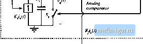 Control input Charge conlroilei Iig. 12.37 Buck cunvL-rter with charge controller, Problem 12.11, 12.11 Figure 1Z37 shows a buck converter with a charge controller 14j. Operation ofthe charge controller is similar to operation of the current-programmed controller. At itie beginning of each switcliing period, at time ; = 0, a sliort clock pulse sets the SR latcti. The logic high signal at ttie Q output ofthe latcti turns the power MOSPET on. At the same time, the logic low signal at the Q output of the latch tuins the switcli 5j off. Current Kf proportional to ttie power .MOSFtTT current ctiarges ttie capacitor C. At i =fTj, ttie capacitor voltage vlf) readies the control input voltage/Г/ ttie cnmparator output goes higti and resets the latch. Tlie logic low signal at the Q output of the latch turns the power MOSFET off At ttie same time, ttie logic tiigh signal at ttie Q output of the latch turns the switcti !>, on, wtiicti quickly discharges the capacitor C, to zero. In this problem, the converter and controller parameters are: - 24 V,= \iT - 100 kHz, L = 60fcH, C= 100Цр, I{ = 3 Q, KfTJC, = 1 ii. You can assume that the converter operates in continuous conduction mode. {л) Find expressions foi the average values of ttie switch network teiminal waveforms, and tience derive a large-signal averaged switch model ofthe buck switch netwnrk with charge control. Tlie control input to itie model is the control current i,. Ttie averaged switch model stiould consist of a current source and a power source. Ttie switch duty cycle d should not appear in the model. (b) Using the averaged switcti model derived in part (a), find an expression for the quiescent output voltage V as a function of Y, I.,anAR. Given = 2 A, find numerical values for V, }y j, and the duty cycle D. For this quiescent operating point, sketcti the waveforms iylj). iiOi and v (/) during one switching period. (c) Perturb and linearize the averaged switcti model from part (a) to derive a small-signa] averaged switch model for the buck switch network with charge control. Find analytical expressions for all parameler values in [erms оГ (he convener parameters and the ijuieseenl operadng tondilions. Skelth (he ttinoplete small-signal notKlel of (he buck converter wilh the charge tonlroller. (d) Solve lhe mode! obtained in pari (c) lo find lhe conlrol-lo-oulpul transfer funclion G,j{,s)-= vlt At the quiescent operating point found in part (b), constmct the Bode plot for the magnitude of tjjand label all salient features uf the magnitude respunse. (e) Comment on advantages charge control may have compared to duty-cycle control or current-programmed control. 12.12 Figure 12.38 shtiws a buck converter wilh a one-cycle controller [15]. Operation нГ lhe one-cycle controller is similar to operation of the current-programmed controller. At the beginning of each .switching period, at time r = 0, a short clock pulse sets (he SR latch. The logic high signal at the Q output of the latch turns the ptjwer MOSFET oti. At the same lime, the logic low signal at lhe Q tiutpul uf the latch turns lhe swiich .9 off Current СчО) proportional to the voltage rff) charges the capacitor C\. At t-di\, lhe capaoilor vollage v(r) reuches the control input voltiige v., lhe comparator output goes high and resets the laith. The logic low signal at the Q outpui of the laith turns lhe power MOSFKT off At the same lime, the logic high signal al the Q outptit of the latch turns the switch on, which quickly discharges the capacitor C, lo lero, In this problem, ihe converter and controller parameters aie: - 24 V,- \IT - 100 кН/ /, = бОр.Н, C= too pF, = 3 П, GTJC = 1. Yoti can assume that the converter operates in the continuous conduction mode. (a) Find expressions for the average values of the swiich network terminiil waveforms, and hence derive a large-signal averaged switch model of lhe buck swiich network wilh one-cycle control. The control input tn lhe model is the control vollage f., The swiich duly cycle d should not appear in the model. ; Switch network 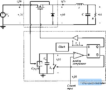 Fig. 12.38 Uuck converter willnjiit-cycle Ltiillraller. Pioblcin 12.12. |
|||||||||||||||