 | |
|
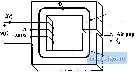
Строительный блокнот Introduction to electronics Node (b) Node Ф, = Фг + Фз *l \ *3 Fig. 13.10 Kirdiuffs current law, аррИйй to magnetic circuits: tlie net flux entering a node must 1ж zero: (a) physical element, in wliieh thnee legs of a ct)re meet at a node; (b) magnetic circuit model. elements such as cores anil air gaps, can be representei] using equivalent magnetic circttits. These magnetic circuits can then be solved using conventional circuit analysis, to determine the various fluxes, MMFs, and terminal voltages and currents. KircholTs laws apply to magnetic circuits, and follow directiy from Maxwells equations. The analog of Kirchoffs current law holds because the divergence of В is zero, and hence magnetic flux lines are continuous and cannot end. Therefore, any flux line that enters a tiode must leave the tiode. As illustrated in Fig. 13.10, the total flux entering anode tnust be zero. The analog of Kirchoffs voltage law follows from Amperes law, Eq. (13.7). The left-hand-side integral in Eq. (13.7) is the sum ofthe MMFs across the reluctances around the closed path. The right-hand-side ofEq. (13.7) states that currents m windings are sources of MMF. An и-turn winding carrying current /(r) can be modeled as an MMF source, analogous to a voltage source, of value rtt(f). When these MMF sources are included, the total MMF around a closed path is zero. Consider the inductor with air gap of Fig. 13.11(a). A closed path following the magnetic field iities is illustrated. This path passes through the core, of pertneabiiity/l ;md length f, mdacToss the air gap, of permeability and length The cross-sectional areas ofthe core and air gap are approximately equal. Application of Amperes law for this path leads to (13.26) where and 3 are the MMFs across the core and air gap, respectively. The core and air gap characteristics can be modeled by reluctances as in Fig. 13.9 and Eq. (13.25); the core reluctance and air gap reluctance are given by Core permeability Ц Cross-sectional area A,  Magnetic path length f -д,- ni{i) Fig, 13.11 Itiductor with air gap example: (a) physical geometry, (b) magnetic circuit model. (13.27) A magnetic circait corresponding to Eqs, (13.2Й) and (13.27) is given in Fig, 13.11(b). The winding is a source of MMF, ofvalue ni. The core and aii gap reluctances are effectively in series. The solution of the magnetic circuit is The flux Ф(0 passes through the winding, and so we can use Faradays law to write . Ф(() v(0 = n Use ofEq. (13.28) to eliminate Ф(г) yields Therefore, the inditctance L is (13,28) (13.29) (13.30) (13.31) The air gap increases the total reluctance of the magnetic circuit, and decreases the inductance. Air gaps are employed in practical inductors for two reasons. With no air gap {i = 0), the indtictance is directly proportional to the core permeability д. This quantity is dependent on temperature and operating point, and is difficult to control. Hence, it may he difficult toconstruct an inductor having a well-controlled value of L. Addition of an air gap having a reluctance greater than li/i. causes the value ofZ, in Eq. (13.31) to be insensitive to variations in p. Addition of an air gap also allows the inductor to operate at higher values of winding current i{t) without saturation. The total flux Ф is plotted vs. the winding MMF ni in Fig. 13.12. Since Ф is proportional to S, and when the core is not saturated ni is proportional to the magnetic field strength H in the Ф=ДА, Fig, 13.12 Effect of air gap on the magnetic circuit Ф vs. iii characteristics. The air gap increases the current f at the onset of core saturation.
13.2 Тгапфппег Hcdeling core, Fig. 13.12 lias the same shape as the core В-Я characteristic. When the core is not saturated. Ф is related to ni according to the linear relationship ofEq. (13.28). When the coresaturates, Ф is equal to Ф.-В, Л, (13.32) The winding current I. at the onset of saturation is found by substitution ofEq. (13.32) into (13.28): The Ф-П1 characteristics are plotted in Fig. 13.12 for two cases: (a) air gap present, and (b) no air gap (i = 0). It can be seen that l is increased by addition of an air gap. Thus, the air gap allows increase of the .saturation current, at the expense of decreased inductance. 13.2 TRANSFORMER MODELING Consider next the two-winding transformer of Fig. 13.13. The core has cross-sectional area A., mean magnetic path length and permeability Д. An equivalent magnetic circuit is given in Fig. 13.14. The core reluctance is (13.34) Since there arc two windings in this example, it is necessary to determine the relative polarities ofthe MIVIF generators. Amperes law states that (13.35) Fig. 13.13 A two-winding transformer. Core urns 2(> Fig. 13.14 Magnetic circuit that models the two-winding transformer of Fig. 13.14, -ЛЛг- |
||||||||||||