
|
| |
|
Строительный блокнот Introduction to electronics The MMF generators are additive, becanse the ciittents i and pass iti the same direttion through the core window. Solution oi Fig. 13.14 yields Ф.Л = 1(, +1гг. This expression could also be obtained by substitution of = Фй? into Eq. (13.35). (13.36) 13.2.1 The Ideal Transformer In the ideal transformer, the core reluctance approaches zero. The causes the core MMF= Фй to also approach zero. Equation (13.35) then becomes 0- n,i, + tifi., (13.37) Also, by Faradays law, we have Note that Ф is the same in both equations above: the same total flttx links both windings. Elimination of Ф leads to V, V, III ll (13,39) Equations (13.37) and (13.39) are the equations of the ideal transformer: = and л,(1-1-(,п = 0 (13,40) (13,38) I 2 Ideal Fig, 13.15 Ideal transformer .symbol. The ideal transformer symbol of Fig. 13.15 is defined by Eq. (13.40). 13.2.2 The Magnetizing Inductance For the actual case in which the core reluctance ifi is nonzero, we have Ф.Л = /1]+ with 1! = ! (13.41) Elimination of Ф yields - i d ~ Mdt (13.42) 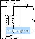 Hg. 13,16 Transformei model including miigneliiitig inductance. This equarion is of tlie form where (13.43) l.u = i -I- Il 113,44) are the magnetizing inductance and magneiizing ctirrent, referred to the primary winding. An equivalent circuit is illustrated in Fig. 13.16. Figure 13.16 coincides with the transformer model introduced in Chapter 6. The magnetizing inductance models the magnetization ofthe core material. It is a real, physical inductor, which exhibits sattiration and hysteresis. All physical transformers must contain a magnetizing inductance. Forexample, suppose that we disconnect the sectmdary winding. We are then left with a single winding on a magnetic core-an indtictor. Indeed, the equivalent circuit of Fig. 13.16 predicts this behavior, via the magnetizing inductance. The magnetizing current causes the ratio of the winding currents to differ from the turns ratio. The transformer saturates when the core flux density B(t) exceeds the saturation fltix density When the transformer saturates, the magnetizing current i,(f) becomes large, the impedance ofthe magnetizing indtictance becomes small, and the transformer windings become short circuits. It should be noted that large winding currents i,(() and ((O do not necessaiiiy cause saturation: if these currents obey Eq. (13.37), then the magnetizing current is zero and there is no net magnetization of the core. Rather, saturation of a transformer is a function of the applied volt-seconds. The magnetizing cutrent is given by Alternatively, Eq. (13.45) can be expressed in terras of the core flux density B(t) as v,(/)rff (13,45) (13.46) The flux density and magnetizing current will become large enough to saturate the core when the applied volt-seconds Aiis too large, where Л, is defined for a periodic ac voltage waveform as (13,47) Ttie limits are chosen such that the integral is taken over the positive portion of the applied periodic voltage waveform. To fix a saturating transforiner, the flux density should be decreased by increasing the number of turns, or by increasing the core cross-sectional areaAj. Adding an air gap has no effect on saturation of conventional transformers, since it does not modify Eq. (13.46). An air gap simply makes the tronsformer less idctd, by decreasing Lf and increasing ((0 without changing B{i). Saturation mechanisms in tims-formers differ from those of inductors, because trfinsformer sfiturfition is determined by the Eipplied winding voltage waveform.s, rather than the applied winding currents. 13.2.3 LEfi](ag Inductances In practice, there is some flux which links one winding but not the other, by leaking into the air or by some other mechanism. As illustrated in Fig. 13.17, this flux leads to leakage indiictance, i.e., additional effective inductances that are in series with die windings, A topologically equivalent structure is illustrated in Fig. 13.17(b), in which the leakage fluxes and arc shown exphcitly as separate inductors. -Ф.. 2(f) v,(0 Fig, 13.17 Leakage flux in a two-winding transformer: (a) transformer geometry, (b) an equivalent systBni. |