
|
| |
|
Строительный блокнот Introduction to electronics 13.2 Transformer Modeling SftS Ftg. 13.18 IXvo-windiiiE transformer equivalent tireuit, ingJutiing magnetizing inductance referred to primary, and primary and secondary leakage inductances. Figtire 13.18 iiltistrates a transformer electrical equivalent circtiit model, incltiding series inductors L([ and which model tiie lealcage inductances. Tliese leakage inductances cause tlie terminal voltage ratio fjCfyVi(f) to differ from the ideal turns ratio л/ ,. In general, the terminal equations of a two-winding transformer can be written
The quantity is called the mutual inductance, and is given by l-n = The quantities i-, I and Li are called the primary and secondary self-inductances, given by (13.48) ((3.49) (13.50) Note that Eq. (13.48) does not explicitly identify the physical turns ratio Hj/ttp Rather, Eq. (13.4S) expresses the transformer behavior as a function of electrical quantities alone. Equation (13.48) can be used, however, to define the effective turns ratio (13.51) and the coupling coefficient V -I [23 (13.52) The cotipling coefficient к lies in the range 0 < < 1, and is a measure of the degree of magnetic coupling between the primary and secondary windings. In a transformer with perfect coupling, the iealcage indtic-tances L([ and are zero. The coupling coefficientis then eqtial to 1. Construction of low-voltage transformers having coefficients in excess of 0.99 is quite feasible. When the coupling coefficient is close to 1, then the effective turns ratio is approximately equal to the physical turns ratio nln 13.3 LOSS MECHANISMS IN MAGNETIC DEVICES 13.3.1 Core Loss Energy is required lo effeci i\ change in the magneiizalion of a core material. Nol all of this energy is recoverable in elecirical form; a fraction is lost as heat. This power loss can be observed electrically as hysteresis of the B-H loop. Consider an н-iurn inductor excited by periodic waveforms v(t) and ((f) having frequency / The net energy that Hows into the inductor over one cycle is (1.153) We can relate this expression to the core B-H characteristic: substitute B(t} for vU) using Faradays law, Eq. (13.13), and substitute Я(г) for i(f) using Amperes law, i.e. Eq. (13.14): <m(t) (13.54) [IdB The lermA.£, is the volume of the core, while the integral is the area of the B-H loop: (energy lost per cycle) ~ (core volurae)(area of B-H loop) (13.55) The hysteresis power loss Pfj is equal to the energy lost per cycle, multiplied hy the excitation frequency /: (13.56) To the extent that the size of the hysteresis кюр is independent of frequency, hysteresis loss increases directly with operating frequency. Magnetic core materiids are iron alloys dial, unfortunately, are also good electrical conductors. As a result, ac magnetic fields can cause electrical etidy currents to flow within the core material itself. An example is illustrated in Fig. 13.19. The ac flux Ф(/) passes through the core. This induces eddy currents i(f) which, according to Lenzs law, flow in paths that oppose the time-varying Ilux Ф((), These eddy Currents cause iR losses in the resistance of the core material. The eddy currenl losses are especially significant in high-frequency applications. According to Faradays law, the ac Ilux Ф((> induces vollage in the core, which drives the current around the paths illustrated in Fig. 13.19. Since the induced voltage is proportional to the derivative of the ilux, the voltage magnitude increases directly wilh the excitation frequency/ If the impedance of 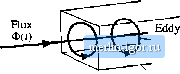 current Core Fiij. 13.14 Lddy currents in an iron core. the tore material is purely resistive and independent of frequency, then the magnitude of the induced eddy currents also increases directly with/. This implies that the ifieddy current losses should increase asf. In power ferrite materials, the core material impedance magnittide actually decreases with increasing/. Over the useful frequency range, the eddy current losses typically increase faster than/. There is a basic tradeoff between saturation tlux density and core loss. Use of a high operating flux density leads to reduced size, weight, and cost. Silicon steel and similar materials exhibit sattiration flux densities of 1.5 to 2 T. Unftjrtunately, the.se core materials exhibit high core kxs.s. In particular, the low resistivity of these materials leads to high eddy current loss. Hence, these materials are suitable for filter inductor and low-frequency transformer applications. The core material is produced in laminations or thin ribbons, to reduce the eddy current magnitude. Other ferrous alloys may contain molyixienura, cobalt, or other elements, and exhibit somewhat lower core loss as well as somewhat lower saturation flux densities. Iron alloys are also employed in powdered ctjres, ctmtaining ferromagnetic particles tjf sufficiently small diameter such that eddy currents are small. These particles are bound together using an insulating medium. Powdered iron and molybdenum permalloy powder cores exhibit typical saturation flux densities of 0.6 to 0.8 T, with core losses significantly lower than laminated ferrous alkiy materials. The insulating nieditim behaves effectively as a distribtited air gap, and hence these ctwes have relatively low permeability. Powder cores find application as transformers al frequencies of several kHz, and as filter inductors in high freqtiency (1(1) kHz) switching converters. Amorphous alloys exhibit low hysteresis loss. Core conductivity and eddy current losses are somewhat lower than ferrous alloys, but higher than ferrites. Saturation flux densities in the range 0.6 to 1.5 T are obtained. Ferrite cores are ceramic materials having low saturation iltix density, 0.25 to 0.5 T. Their lesisdvilies are nnuch higher than other materials, and hence eddy current losses are much smaller. Manganese-zinc ferrite cores find widespread use as inductors and transtorniers in converters having switching frequencies of 10 kHz to 1 MHz. Nickel-zinc ferrite materials can be employed at yet higher frequencies. Figure 13.20 contains typical total core loss data, for a certain ferrite material. Power loss density, in Walts per cubic centimeter of core material, is plotted as a function of sinusoidal excitation frequency / and peak ac flux density ДЯ, At a given frequency, the core loss P can tie approximated by an empirical function of the form <5 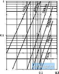 0.01 0.01 AB. Tesla The parameters Kj. and are determined by fitting Eq. (13.57) to the manufacturers published data. Typical values of P for ferrite materials operating in their intended range of ДВ and/ lie in the range 2.6 to 2.S. The constant of proportionality Kj, increases rapidly with excitation frequency /. The dependence of Kj tm/can also be approximated by empirical formulae that are fitted to the manu- Fig. 13.20 Topical core loss data for a high-frequency power ferrite material. Power lo.4s density i.s plotted v,-;, pedic ac flux density ДР, fur sinusoidal excitation. |