
|
| |
|
Строительный блокнот Introduction to electronics SJ Coiislivclioii of EqiiKiileia Circtiii Model 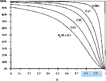 Fig. 3.IS Efficiency vs. tluLy cycie, boosi convener with inductor copper loss. 3.15 that the efficiency is typically high at low duty cycle.4, but decreases rapidly to zero near D = 1. Thus, the basic dc transformer model can be refined to include other effects, such as the inductor copper loss. The model describes the basic properties of the converter, including (a) transformation of dc voltage and current levels, (b) second-order effects such as power los.ses. and (c) the conversion ratio m. The model can be solved to find not only the output voltage V, but also the inductor citrrent / and the efficiency fi. All of the well-known techniques of circuit analysis can be employed to solve the model, making this a powerful and versatile approach. The example considered so far is a relatively simple one. in which there is only a single loss element. Of course, real converters are considerably more complicated, and contain a large number of loss elements. When solving a complicated circuit to find the output voltage and efficiency, it behooves the engineer to use the simplest and most physically meaningful method possible. Writing a large number of simultaneous loop or node equations is not the best approach, because its solution typically requires several pages of algebra, and the engineer usually makes algebra mistakes along the way. The practicing engineer often gives up before finding the correct solution, The equivalent circuit approach avoids this situation, becaitse one can simplify the circuit via well-known circuit manipulations such as pushing the circuit elements to the secotidary side of the transformer. Often the answer can then be written by inspection, using the voltage divider rule or other formulas. The engineer develops confidence that the result is correct, and does tiot contain algebra mistakes. Fig, 3.16 Buck converter cxiiinplc. 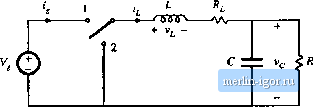 HOW TO OBTAIN THE INPUT PORT OF THE MODEL Lets try to derive the model of the buck converter of Fig. 3,16, using the procedure of Section 3.3. The inductor winding resistance is again modeled by a series resistor R,. The average inductor voltage can be shown to be (3.24) This e(]uation describes a loop with the dc inductor currentThe dc components of the voltages around this loop are: (() the DV term, mt)deled as a dependent voltage source, (ii) a voltage drop I,R modeled as resistor R, and (iii) the dc output voltage Vf., The average capacitor current is W = 0 = /,- (3.25) This equation de.scribes the dc currents flowing into the node connected to the capacitor. The dc component of inductor current, f, flows into this nt)de. The dc load current VJR(\.z., the current flowing through the load resistor R) flows out of this node, An equivalent circuit that models Eqs. (3.24) and (3.25) is given in Fig. 3.17. This circuit can be solved to determine the dc output voltage V. What happened to the dc transformer in Fig, 3,17? We expect the buck converter model to contain a dc transformer, with turns ratio equal to the dc conversion ratio, or \\D. According to Fig. 3.2, the secondary of this transformer is equivalent to a dependent voltage source, ofvalue ZJV,. Such a source does indeed appear in Fig. 3.17. But where is the primary? From Fig. 3.2, we expect the primary of the dc transformer to be equivalent to a dependent current source. In generah to derive this source, it is necessary to find the dc comptment of the converter input current ijj). The converter input current waveform ijj) is sketched in Fig. 3, IS, When the switch is in position I, 1,(0 is equal to the inductor current. Neglecting the inductor current ripple, we have ip) = When the switch is in position 2, i{t) is zero. The dc component, or average value, oii(t) is Fig. 3.17 Equiralcm circuit derived Iroin Hqs. (3,24) and (3,25), 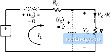 Ш - Ftg. 3,18 Converter input current waveform ijit). 3.4 How lo Ohlain ihe Inpui Port of the Model 51
Fig. 3.19 Converter input port dc equivalent circuit. 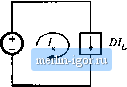 Fig. 3,20 The circuits of Figs, 3,17 and 3.19, drawn together. 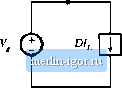 Fig. 3.21 Equivalent circuit of the buck converter, including a 1;D dc transformer and the inductor winding resistance R,, 1 :D - -VV- it)dtDI The integral of is equal to the area under the ((f) curve, mDTJ according to Fig. 3.18. The dc component 1 is therefore (DTi)IT = DI. Equation (3.2Й) states that l, the dc component of current drawn by the converter out of the source, is equal to 0/- An equivalent circuit is given in Fig. 3.19. A complete model for the buck converter can now be obtained by combining Figs. 3.17 and 3.19 to obtain Fig. 3.2(). The dependent current and voltage sources can be combined into a dc transformer, since the DV dependent voltage source has value D times the voltage V across the dependent current source, and the current source is the same constant D times the ctirrent I, through the dependent voltage source. So, according to Fig. 3.2, the sources are equivalent to a dc transformer with turns ratio 1:D, as shown in Fig. 3.21. In general, to obtain a complete dc equivalent circuit that models the converter input port, it is necessary to write an equation for the dc component of the converter input current. An equivalent circuit |
|||||||||