
|
| |
|
Строительный блокнот Introduction to electronics factiirers published data; a fourth-order polynomial or a fimction of the form Kjf are sometimes employed for this рофове. 13.3.2 Low-Frequency Copper Loss Significant loss also occurs in the resistance of the copper windings. This is also a major determinant of the size of a magnetic device: if copper loss and winding resistance were irrelevant, then inductor and transformer elements could he made arbitrarily small by tiseofmany small turns of small wire. Figure 1121 contains an equivalent circtiit of a winding, in which element R nuKlels the winding resistance. The copper loss of the winding is (13.58) where is the rms value of !(r). The dc resistance of the winding conductor can be expressed as (13.59) Fig. 13.21 Winding equivalent circuit that models copper loss. where is the wire bare cross-sectional area, and ,is the length of the wire. The resistivity p is equal to L724-10 iJ-cm for soft-annealed copper at room temperature. This resistivity increases to 2,3 - lO-flni at 10()°C. 13.4 EDDY CURRENTS IN WINDlNt; CONDUCTORS Eddy currents also cause power losses in winding conductors. This can lead to copper losses significantly in excess of the value predicted by Eqs. (13.58) and (13.59). The specific conductor eddy current mechanisms are called the skin effect and the pioxiinity effect. These mechanisms are most pronounced in high-current conductors of multi-layer windings, particularly in high-frequency converters. 13.4.1 Introduction to the Skin and Proximity Effects Figure 13.22(a) illustrates a current i(/) tlowing through a solitary conductor. This current induces magnetic Ilux Ф((). whose flux lines folk)w circular paths around the current as shown. According to Lenzs law, the ac flux in the conductor induces eddy currents, which flow in a manner that tends to oppose the ac ПихФ(г). Figure 13.22(h) illustrates the paths of the eddy currents. It can be seen that the eddy currents tend to reduce the net ctirrent density in the center of the conductor, and increase the net current density near the surface of the conductor. The current distribution within the conductor can tie found by solution of Maxwells equations. For a sinusoidal current iit) of frequency/ the result is that the current density is greatest at the surface of the condtictor. The current den.sity is an exponentially decaying function of distance into the conductor, with characteristic length 5 known as the penetration deptli or skin depth. The penetration depth is given 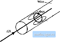 Current density J Eddy currems 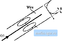 Eddy currents Fig, 13,22 The skin effect: (a) current i[t) induces йил ФО), which in turn induces eddy 4;urrents in conductor; (b) the eddy currents tend lo oppose the cutrent i{t) in the center of the wire, and increase the current on the jutface of the wire. (13.60) For a ctipper conductor, the permeability is equal to IL(, and the resistivity p is given in Sectitm 13.3.2. Al iriO°C, the penetration depth of a ctipper ctmductor is 5 = cm (13.61) vtilh/expiessed in FIz. The penetratitm depth of copper ctmduetors is plotted in Fig. 13.23. as a function offrequency /! For comparison, the wire diameters rfof standard American Wire Gauge (AWC) conductors are also listed. It can be seen that dtb = 1 for AWG #40 at approximately 5(1) IcHz, while = 1 for Penetration depth 5, cm 0.01 0.001 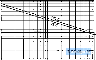 10 kHz 100 kHz Frequency Wire diameter Ъ #20 AWG T WO AWG r #40 AWG IMHz Fig. 13.23 Penetration depth 5, as a function of frequency/, for copper wire. Currettt density j Area AWG #11 ar approximately 10 kHz. The .skin effect canses the resistance and copper lo.ss of solitary large-diameter wires to increase at high frequency. High-frequeney currents do not penetrate to the center of the conductor. The current crowds at the surface of the wire, the inside of the wire is not utilized, and the effective wire cross-sectional area is reduced. However, the skin effect alone is not sufficient to explain the increased high-frequency cupper losses observed in multiple-layer transformer windings. A conductor that carries a high-frequency current ;(r) induces copper loss in a adjacent conductor by a phenomenon known as the proximity effect. Figure 13.24 illustrates two copper foil conductors that are placed in close proximity to each other. Conductor 1 carries a high-frequency sinusoidal current i{t), whose penetration depth 5 is much smaller than the thickness !i of conductors I or 2. Conductor 2 is open-circuited, so that it carries a net current of zero. However, it is possible for eddy currents to be induced in conductor 2 hy the current i(t) flowing in conductor I. The current f(r) flowing in conductor I generates a flux Ф(0 in the space between conductors I and 2; this flux attempts to penetrate conductor 2. By Lenzs law, a current is induced on the adjacent (left) side of conductor 2, which tends to appose the flux Ф((), If the conductors are closely spaced, and if li vv- 6, theu the induced current will be equal and opposite to the current /(f), as illustrated in Fig. 13.24. Since conductor 2 is open-circuited, the net current in conductor 2 must be zero. Therefore, a current + ((/) Hows on the right-side surface of conductor 2. So the current flowing in conductor 1 induces a cunent that circulates on the surfaces of conductor 2, Figure 13.25 illustrates the proximity effect in a simple transformer winding. The primary winding consists of three series-connected turns of copper foil, having thickness li 5, and carrying net current f(f). The secondary winding is identical; to the extent that the inagnetizing current is small, the secondaty turns carry net current - /(f). The windings are surrounded by a magnetic core material that encloses the mutual flux of the transformer. The high-frequency sinusoidal current ((f) flows on the right surface of primary layer 1, adjacent to layer 2. This induces a copper loss in layer 1, which can be calculated as follows. Let R be the dc resistance of layer 1, given by Eq. (13.59), and let ! be the rms value of ((f). The skin effect causes the copper io.4s in layer I to be equal to the loss in a conductor ofthickness 5 with uniform cuirent density. This reduction of the conductor thickness from h to 5 effectively increases the resistance by the same factor. Hence, layer 1 can be viewed as having an ac resistance given by 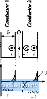 Fig. 13.24 lhe proximity effect in adjacent coppei foil cxinductors. Coiiductoi- I carries cuireni i{l). Coiiducior 2 i.s t)pe)i-ciix:uited. (13.62) The copper loss in layer 1 is (1,3.63) The proximity effect causes a current to be induced in the adjacent (left-side) surface of primary layer 2, which tends to oppose the flux generated by the current of layer 1. If the conductors are closely spaced, and if/i s> S, then the induced current will be equal and opposite to the current t(f), as illustrated |