
 | |
Строительный блокнот Introduction to electronics 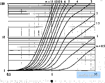 Fig. 13.31 Increase of layer topper loss due to (he proximiiy effect, as a funclion of (p and MMF ratio ni, for sinusoidal excitation. m= 15 12 10 8 -L=t 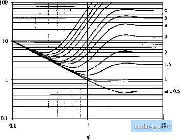 Fig. 13.33 Layer copper loss, relative to the dc loss in a layer having etfective thickness of one penetraUott depth. Primary layers Secondary layers Fig, 13,33 Conventional tWD-winding transformer cxamiilc. Each windiiif; consists of Л1 layers. 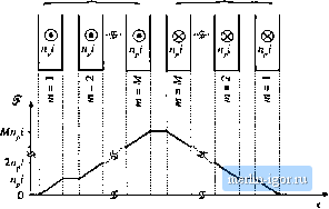 13.4,5 Example: Power Loss in a Transformer Winding Let us again consider the proxinrity loss in a conventional transformer, in which the priinary and secondary windings each consist of M layers. The normalized MMF diagram is illustrated m Fig. 13.33. As given by Eq. (13.81), the proximity effect increases the copper loss in each layer hy the factor фб((р, ). The total increase in primary winding copper loss P,-is found by summation overall of the primary lay- (i3.s3) Owing to the symmetry of the windings in this example, the secondary winding copper loss is increased hy the same factor Upon substituting Eq. (13.80) and collecting tenns, we obtain P f m-[га(Ц1) -4f;,((j))j - m[2(JI(Ф) - 46з(Ф)) + (S (Ф) The summation can be expressed in clo.sed form with the help of the identities {13,S4) M\M \\ m - M, , MfM-r-l][2,W+l) (I3.HS) Use of these identities to simplify Eq. (13.84) leads to (13.Hfi) This expression is plotted in Fig. 13.34, for several vaiues af M. For large (p. Cjftp) tends to 1, while Nutt,ber of layers M = \5n}Qi 7 6 S 4 =D- 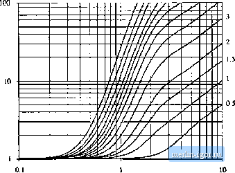 Fi;, 13.34 Increased toial winding copper loss in the two-wiiidiiig tmn4ftirme[ example as a Function of ф antl number of layers M, for siimsoidtil excitatinn. Number of layerx Л/= 15 12 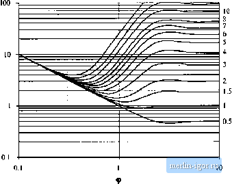 Hg. 12.35 Iransfomiei example ivtnditig total topper lots, relative to tlie ivintling dt loss forlaycts having effective ihicknesRes of one penetration deptli. |