
|
| |
|
Строительный блокнот Introduction to electronics Fig. 13,38 Pulse-width (iiocljlatecl winding current waveform. 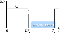 loss. The skin depth 5 is smaller for high frequency harmonica than for the fundamental, and hence the wavefortn hatynonics exhibit an increased effective (p. Let ф, be given by Ec]. (13,73), in which 5 is found hy evaluation ofEq. (13.60) at the fundamental frequency. Since the penetration depth 6 varies as the inverse square-root of frequency, the effective value of ip for harmonic, у is (13,94) In a multiple-layer winding excited by a current waveform whose fundamental component has ф = ф, close to 1, harmonics can significantly increase the total copper loss. This occius because, for m > 1, Q(fp, m) is a rapidly increasing function of ф in the vicinity of 1. When ф, is sufficiently greater than 1, then 0:{ф, >п)л& nearly constant, and harmonics have less influence on the total copper loss. For exaraple, suppose that the two-winding transformer of Fig. 13.33 is employed in a converter such as the forward converter, in which a winding current waveform /(/) can be well approximated by the Fourier series ofEq. (13.93). The winding contains Л/layers, and has dc resistance S , . The copper loss induced by the dc component is (13,95) The copper loss Fj ascribable to harmonic j is found by evaluation ofEq. (13.86) with ф = ф; G t(77 Ф,) +1W - 1) (Ci(,/7 Ф,) - 2G?,(v7 Ф, (13.96) The total copper loss in the winding is the sutn of losses arising from all components of the hitrmonic series: G ,(v7 Ф,) I (Af - 1) IС ,(v7 4 1) - 2C,(v7 Ф i) (1Э.Э7) In Eq. (13.97), the copper loss is expressed relative to the loss Л, predicted by a low-frequency analysis. This expression can be evahiated by use of a computer program or computer spreadsheet. To explicitly quantify the effects of harmonics, we can define the harmonic loss factor as F -i (13.98) vith p. given by Eq. (13.96). The total winding copper loss is then given by Fig. 13.39 [ncrcased proximity losses induced l>y PWM wnveform liiirinonics, foi-waid converter example: (a) at D = 0, [, (b) atD = 03,(c) at = 0,5. 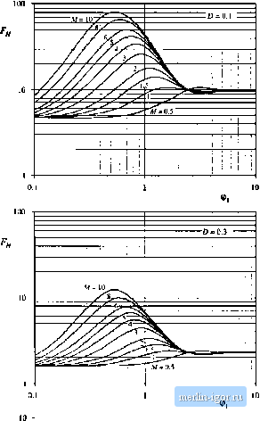
P.. = X.WX, (13.99) with given by Eq. (13.86). The harmonic factoris a function not only of the winding geometry, but also of the harmonic spectrtim of the winding current waveform. The harmonic factor Fj is plotted in Fig. 13.39 for several valties of D, for the simple transformer example. The total harmonic distortion (THD) ofthe example current waveforms are: 48% for D = 0.5, 76% for D = 0.3, and 191% for D = 0.1. The wavefortn THD is defined as It can be seen that harmonics significantly increase the proximity loss of a multilayer winding when ф is close to 1. For suffictently small ф), the proximity effect can be neglected, and F tends to the value 1 + (THD), For large (();, the harmonics also increase the proximity loss; however, the increase is less dramatic than for ф, near 1 because the fundamental component proximity loss is large. Il can he concluded that, when the current waveform contains high THD and when the winding contains several layers or more, then proximity losses can he kept low only by choosing ф, much less than 1. Interleaving the windings allows a larger value of ф, to be employed. 13.5 SEVERAL TYPES OF IMACINETIC DEVICES, THEIR B-H LOOPS, AND CORE VS. COPPER LOSS A variety of magnetic elements are commonly used in power applications, which employ the properties of magnetic core materials and windings tn different ways. As a result, quite a few factors constrain the design of a magnetic device. The maximum flux density must not saturate the core. The pealt ac flux density should also be sufficiently small, such that core losses are acceptably low. The wire size should be sufficiently small, to fit the required nutnber of turns in the core window. Subject to this constraint, the wire cross-sectional area should be as laige as possible, to minimize the winding dc resistance and copper loss. But if the wire is too thic);, then unacceptable copper losses occur owing to the proximity effect. An air gap is needed when the device stores significant energy. But an air gap is undesirable in transformer applications. It should be apparent that, for a given magnetic device, some of these constraints are active while others are not significant. Thus, design of a magnetic element involves not only obtaining the desired inductance or turns ratio, but also ensuring that the core material does not saturate and that the total power loss is not too large. Several common power applications of magnetics are discussed in this section, which illustrate the factors governing the choice of core material, maximum flux density, and design approach. 13.5.1 Filter Inductor A filter inductor employed in a CCIM bticlt converter is illustrated in Fig, 13.4f)(a), In this application, the value of inductance L is usually chosen such that the inductor current ripple peak magnitude Ai is a small fraction of the fuil-ioad inductor current dc coinponent /, as illustrated in Fig. 13.40(b). As illustrated in Fig. 13.41, an air gap is employed that is sufficiently large to prevent saturation ofthe core by the pealc current / + Ai. |