
|
| |
Строительный блокнот Introduction to electronics  Fig. 13,40 Filter inductor employed in a CCM buck converter: (ii) circuit schematic, (b] inductor current waveform. Core reluctance 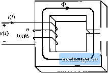 NJ Air gap X rel reluctance -JW- Fig. 13,41 Filter inductor: (a) structure, (b) magnetic circuit model. The core magnetic field strength MJl) is related to the winding current /(r) according to where f. is the magnetic path length of the core. Since H(t) is proportional to i(t), HJj) can he expressed as a large dc component Яд and a .small superimposed ac ripple ДЯ., wdiere nf ЛЫ - дА/ c (13.102) A sketch of B(f) vs. Нф for this application is given in Fig. 13.41 This device operates with the minor B-H loop illustrated. The size of the minor loop, and hence the core loss, depends on the magnitude of the inductor current ripple Д/. The copper loss depends on the rms inductor current ripple, essentially Minor B-H loop, filter induclor Fig, UAl Filter intluctor minor В-Я loop. 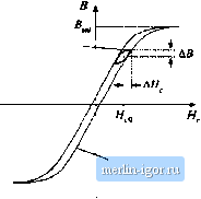 B-H loop, large excitation equal to the dc component 7. Typically, the core loss cati be ignored, and the design is driven by the copper loss. The maximum flux density is limited by satmation of the core. Proximity losses are negligible. Although a high-trequeiicy ferrite material can be employed in this application, other materials having higher core losses and greater saturation tlux density lead to a physically smaller device. Design of a filter inductor in which the maximnm flnx density is a specified value is considered in the next chapter. 13.5.2 AC Inductor An ac itiductor employed in a resonant ctmverter is illustrated iti Fig. 13.43. In this application, the high-frequency current variations are large. In consequence, the B{f)-H{t) bop illustrated in Fig. 13.44 is large. Core loss and proximity loss ate usually significant in this application. The maximum tlux density Fig, 13.43 Ac inductor, resoriant convener example: (a) resonant tank circuit, (b) inductor current waveform. 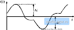 B-H loop, for AS Operalicn as ac induclor Fig, 13,44 Operatiorial В-И loop of an ac inductor 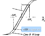 is limited by eore loss rather than saturation. Both tore kiss and copper k)ss must be accounted for in the design of this element, and the peak ac flux density ДВ is a design variable that is typically chosen to minimize the total loss. A high-frequency material having low core loss, such as ferrite, is normally employed. Design of magnetics such as this, in which the ac flux density is a design variable that is cho-.sen in a optimal manner, is considered in Chapter 15. 13.5.3 Transformer Figure 13.45 illustrates a conventional transformer employed in a switching converter. Magnetization of the core is modeled hy the magnetizing inductance L. The magnetizing current i(() is related to the core magnetic field H(r) iccording to Amperes law (13,103) However, iQ) is not a direct function of the winding currents /[(() or /(f). Rather, the magnetizing current is dependent on the applied winding voltage waveform Vj(0. Specifically, the maximum ac Ilux density is directly proportional to the applied volt-seconds . A typical B-H loop for this application is illustrated in Fig. 13.46.
Area X, Fig, 13j45 Conventional transfomier; (a) equivalent circuit, (b) lypical primary voltage and magnetizing current waveforms. Fig. 13fi Operational B-H loop of a conventional transformer. 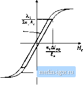 B-H loop, for operation as converiiiCfnal Iransformer - Core B-H loop |
|||||||||