
|
| |
|
Строительный блокнот Introduction to electronics In the transformer application, core loss anil proximity losses are usually significant. Typically the maximutri flux density is limited hy core loss rather than by saturation. A high-frequency material having Itiw c[)re hws is employed. Btith c[)re and C[)pper losses must hie acctmnted 1Ъг in the design [)f the transfonner. The design must aist) incorp[)rate multiple windings. Transformer design with tliix density optimized for minimum total loss is described in Chapter 15. 13.5,4 Coupled Inductor A coupled inductor is a filter inductor having multiple windings. Figure 13.47(a) illustrates coupled inductors in a two-output forward converter. The inductors can be wound on the same core, because the winding voltage waveforms are proportional. The inductors of the SEPIC and Cuk converters, as well as of niultipie-tiutput buck-derived ctmverters and some other converters, can be coupled. The inductttr current ripples ctm be controiicd by control of the winding leakage inductances [12,13]. DC currents flow in each winding as illustrated in Fig. 13.47(b), and the net magnetization ofthe cote is proportional to die sum of the winding ampere-turns: Я,(/) = fiiii(/) + nif2{() йг (13.104) As in the case ofthe single-winding filter inductor, the size of the minor E-H loop is proportional to the total current ripple (Fig. 13.48). Small ripple implies small core loss, as well as small proximity loss. An air gap is employed, and the maximum flux density is typically limited by saturation. Fig. 13.47 Coupling the ouiput filter inductors of a two-output forward converter: (a) schematic, (b) typical inductor current waveforms. 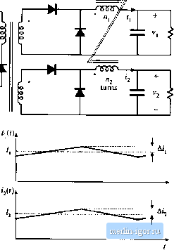 Minor B-H loop, coupled ituiucior Fij 13.4K Coiipkd inductor miiiwa-ZniKip, 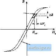 B-H loop, large excitation 13.5.5 Fljback Transformer As (liscussed in Chapter 6, the fiyhack transformer functions as an inductor with two windings. The primary winding is ttsed during the transistor conduction interval, and the secondiuy is used dtiring the diode conduction interval. A flyback converter is iliustrated in Fig. 13.49(a), witli the flyback transforiner modeled as a magnetizing inductance in parallel with an ideal transformer. The magnetizing current ijfU) is proportional to the core magnetic field strength ЯД()-Typical DCM waveforms are given in Fig. 13.49(b). Since the flyhack transfortner stores energy, an air gap is needed. Core loss depends on the magnitude of the ac coinponent of the magnetizing current. The B-H loop for discontinuous conduction mode operation is illustrated in Fig. 13.50. When the converter is designed to operate in DCM, the core loss is significant. The peak ac flux density ДЙ is then chosen to maintain an acceptably hiw core loss. For CCM operation, core ioss is less significant, and the maximum flnx den.sity may be limited only by saturation of the core. In either case, winding proximity losses are typically quite significant. Unfortunately, interieaving the windings has iittle impact on the proximity loss because the primary and secondary winding currents are out of phase. 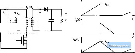 Fig, 13,49 Flyback transiomiei: (a) converter sciieniaiic, with transfumier equivalent circuit, (b) DCM cuirent waveforms. Fig, 13.S0 Operational fiwyiuup uf a DCM flyback iransforniei. 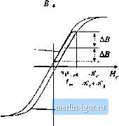 Б-И loop, for operation in ОСИ flyback converler Core B~H loop 13.6 StlMlVtARY OF KEY POINTS 1. Magnelii; devices can be modeleJ using lumped-element magnedc circuits, in a manner iimilar ti) thai commonly used to model electrical circuits. The magnetic analogs of electrical voltage V, current /, and resistance R, are magnetomotive force (MMF) fUlX Ф, and reluctance ,jf respectively. 2. Faradays law relate:: the voltage induced in a loop of wire ti) the derivative id flux passing through the interior of the кюр, 3. Amperes law relates the total MMF around a loop to the total current passing through the center t)f the loop. Amperes law imphes that winding currents are sources of MMF, and that when these sources are included, then the net MMF around li ckjsed path is etjual to zen>. 4. Magnetic ewe materials efthihit hysteresis and saturation. A core material saturates when the flux density В reaches the saturation flux density 5. Air gaps lire employed in inductors to prevent saturation when a given maximum current flows in the winding, and to stabilize the value of inductance. The inductor with air gap can be analyzed using a simple magnetic equivalent circuit, containing cure and air gap reluctances and a source representing the winding MMF 6. Conventional transformers can be modeled using sources representing the MMFs of each winding, and the core MMF. The ctirc reluctance approaches zen> in an ideal transformer. Nonzero ctirc reluctance leads to an electrical transformer model ciintaining a magnetizing inductance, eftectively in parallel with the ideal transfonner. Flux that does not hnk both windings, Dr leakage flux, can be miideled using series inductors. 7. The conventiimal transfDrmer sattirates when the applied winding volt-seconds are loo large. Addition of an air gap has no effect on saturation. Saturation can be prevented by increasing the core cross-secdonal area, or by increasing the number of primary turns. 8. Magnetic materials exhibit core loss, due lo hysteresis ofthe B-H loop and to induced eddy curEents IIdw-ing in the core material. In available core materials, there is a tradeoff between high saturation flux density B and high core loss Рд. Laminated iron alliiy cures exhibit the highest H but also the highest /д., while ferrite cores exhibit the liiwesl Гу but also the liiwest Between these two extremes are powdered irtin alloy and amorphtius alh>y materials. 9. The skin and pniximity effects lead tii eddy currents in winding conductors, which increase the copper loss in high-current high-frequency magnetic devices, When a conductiir has thickness approaching or |