
|
| |
|
Строительный блокнот Introduction to electronics larger Ihjn lhe penetrjlion deplh 5, magnelic fields in the vieinity of lhe eondLiettjr indLiee eddy currents in lhe coEiductiir. Acciirding ti) Lenzs law, these eddy curreEUs llow in paths that lend to iippose the applied magnetic fields, 10. The magnetic field strengths in lhe vicinity of lhe winding conductors can he determined by use of MMF diagrams. These diagrams ase ciinslrucled by applicatiun of Ampere.s law, following the closed paths of the magnetic field lines which pass near the winding conductors. Vlulliple-layer noninterleaved windings can exhibit high niiiximum MMFs, wilh resuldng high eddy currents and high copper loss. 11. An expression for the copper loss in a layer, as a function of the magnetic field strengths or M.MFs surrounding lhe layer, is given in Section 13.4.4. This expression can be used in conjanclinn wilh the MMF diagram, lo compute the copper less in each layer of a winding. The results can then he summed, yielding the total winding copper loss. When the effective layer thickness is near lo or greates than line skin depth, the t:opper losses of multiple-layer noninterleaved windings are greatly increased. 12. Pulse-widlh-modulated winding currents ciintain significant total harmonic distortion, which can lead lo a further increase of copper loss. The increase in proximity loss caused by current harmonics is most pronounced in multiple-liiyer non-interleaved windings, with an effecdve layer thickness neaitine skin depth. References [IJ МП Staff, Magnetic Circuits and Transformers, Cambridge: The MIT Press, 1943. [2] J. K. Watson, Applications of Magnetism. New York: John Wiley & Sons, 19S0. [3] R. P. severns and G. E. Bloom, Modern Dc-to-Dc Switckmode Power Converter Circuits, New York: Vao Nostrand Reinhold, 1985. [4] A. Dalhajre and R. D. Middlebrook, Modeling and Estimation of Leakage Phenoraena in Magnetic Circuits, IEEE PoM-er Electronics Specialists Coiiferci\ce. \Ш) Record, pp. 213-226. [5] S. El-Hamamsy and E. Chang, Magnetics Modeling for Computer-Aided Design of Power Electronics Circuits, IEEE Power Electronics Specialists Conference, I9S9 Record, pp. 635-645. [6] P. L. Dowell, Effects of Eddy Cun-ents in Transformer Windings, Proceedings of the lEE. Vol. 113, No. 8, August 1966, pp. 13S7-I394. [7] M. p. Perry, Multiple Layer Scries Connected Winding Design for Minimum Loss, IEEE Transactions oil Power Apparatus and Systems. Vol. Р.Л.5-98, No. I, Jan./Fet). 1979, pp. 116-123. [g] P. S. Venkatraman, Winding Eddy Current Losses in Switch Mode Power Transformers Due to Rectangular Wave Currents, Proceedings <Powercon 11. 1984, pp. A 1,1 - A LIL [9] B. Carsten, High Frequency Conductor Losses tn Switchmode Magnetics, High Frequency Power Convener Conference, 1986 Record, pp. 155-176. ] 10] J. P. V.andelac and P. ZttXjAS, A Novcl Approach for Minimizing High Frequency Transformer Copper Losses, IEEE Power Electronics Speciali.sts Conference. I9S7 Record, pp. 355-367. [11] A. M. Urljng, V. A. NiEMELA, G. R. Skutt, and T. G. WILSON, Characterizing High-Frcquency Effects in Transformer Windings-A Guide lo Several Significant Articles, IEEE Applied Power Electronics Conference. 1989 Record, pp. 373-3S5. Frohkm.1 [12] S. Йик and R. D. Middlebrook, Coupled-Inductor and Other Extensions of a New Optimum Topology Switching Dc-lo-Dc Converter, IEEE hiduslry AiJplicaltons Socieiy Annual Meeiing, 1977 Proceedings, pp. 1110-1122. [13] S. Chic and Z. Zhang, Coupled-Indue юг Analysis and Design, IEEE Poivnr EUctninici Spacialisls Conference, [Ш Record, pp, 655-665. Problems 13.1 ITic core illustrated in Fig. 13.Sl(a) is 1 cm thick. All legs arc 1 cm wide, except for the right-hand side vertical leg, which is 0.5 era wide, You may neglect nonuniformitics in the flux distribution caused by turning corners. ta) Л лет ......U--!.m.....U 0 5 cm t cm 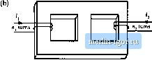 Core relaUve permeabilily = 10(Ю n,= 10 nj = 20 Fig. 13.S1 Fmblem 13.1 (a) Determine the magnetic circuit raodcl of this device, and label the values of all reluctances in your model. (b) Determine the inductance of the winding. A second winding is added to the same core, as shown in Fig. И5 1(b). (c) Modify your model ofpart (a) to include this winding. (d) The electrical equations for this circuit may be written in the form Use superposition to determine analytical expressions and numerical values for .ц, L, and Ljj. 13.2 Two windings arc placed as illustrated in Fig. 13.52(a) on a core of uniforra cross-sectional area Aj, = i ctn. Each winding has 50 turns. The relative permeability of the core is (t = lO *. (a) Sketch an equivalent magnetic circuit, and determine numerical values for each reluctance. (b) Determine the sclf-iiiductanccofcach winding. (c) Determine the inductance С obtained when the windings arc eonncctcd in scries as in Fig. 13.52(b). (d) Determine the inductance U obtained when the windings tue connected in anti-series as in Fig. 13.52(c). tig. 13.52 Problem 13,2, 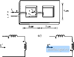 13.4 All three legs of the magnelJL- devJLe illu,slraled in Fig, 13.53 are of uniform cross-settional жеа A-. Legs I and 2 eath have magnetic path length 3£, while leg 3 has magnetic path length f. Both windings have л turns. The йиш htis permeability Д -Ss- )iy. 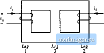 Fig. 13.53 Magnetic core for Problem 13.3. Skelch ii mugnedc equivalent circtiit, and give analytical expressions for all element values. A vollage source is connected to winding 1, such that i(/) is a square wave of peak value V and period Winding 2 h open-circuiled. (b) Sketch (((/)und lubel its peak value. (c) Find the flux (f);(f) in leg 2. Sketch Фз(/) and label its peak value. (d) Sketch Vj(0 and label its peak valne. The magnetic device illustrated in Fig. 13,54(a) consists of two windings, which can replace lhe two inductors in a Ctlk, SEPIC, nr other similar converter. For this problem, all three legs have the same uniform cross-sectional area A , The legs have gaps of lengths Л. and respectively. The core permeability is very large. You may neglect fringing flux. Legs I and 2 have windings containing and turns, respectively. (a) Derive a magnetic circtiit mtjdel for this device, and give analytical expressions for each reluctance in your model. Label lhe polarities of the MMF generators. (b) Write the electrical terminal equations of this device in the matrix form |