
|
| |
|
Строительный блокнот Introduction to electronics Pmbhms
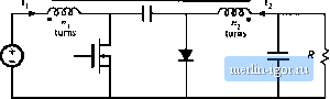 Fig. 13.54 Magneticcore and converter for Prublem 13.4. and derive analytical expressions for L , L,j, and jL;j. (c) Derive an electrical circuit model for this device, and give analytical expressions for the turns rado and each inductance in your model, in terms ofthe turns and Eeluclances ofpart (a). This single magnetic device is lo be used to realize the two inductors ol the tuk converter, as in Fig. 13.54(b). (d) Sketch the voltage waveforms i(r)and v2i), making the linear ripple approximalit>n a.s appropriate. You may assume lhat the converter operates in the continuous coFidtiction mode. (e) The voltage waveforms of part (d) are applied to your model of ptirts (b) and (c). Solve your model to determine the slopes of the inductor current ripples during intervals DT and Ofj, Sketch the steady-slate inductor current waveforms J[(l) anJ 13(1), and label all slopes. (0 By skillful choice ofn/Mj and the air gap lengths, it is possible to make the inductor current ripple hi in either ift) or ij(r) go Ic zero. Determine the conditions on HAij, й[, gj, and that cause the cutEenl Eipple in i{i) to become zero. Sketch the resulting i(t) aEid /;(t), and label ail slopes, It is possible to couple the inductors in this manner, and cause one ofthe inductor curEcnt ripples to go to zero, in any converter in which the inductor voltage waveforms are proportional. 13.5 Over its usable operating range, a certain permanent magEiet material has the B-H chaEacterislics illus- trated by the solid line in Fig. 13.55. The magnet has length l- , - 0.5 cm, and cross-sectional area 4 cm . fl, - 1 T. Derive an equivalent magnetic circuii model for the magnet, and label the numerical values of the elements.
13.6 The Lwo-lransislor forward converter of Fig. 6.27 operates with = 300 V, 28 V. switching frequency= 100 kHz, and turn.!; ratio n = 0.25. The dc lead pcwer is 250 W. The transforiner uses an EC41 ferrite core: relevant data lor this сч)ге is listed in Appendix D. The core lo.ss is given by Fig. 13.20. The primary winding consists of 44 turns of #21 AWG wire, and the secondary winding is composed of 11 turns of #15 AWG wire. Data regarding the American wire gauge is also listed in Appendix D. (a) Estimate the core loss of this transformer (b) Determine the copper kiss of this Iransformer. You may neglect proximity losses. 13.7 The two-uansistor forward ctinverter of Fig. 6.27 operates in CCM with = 300 V, Г= 28 V, switching frequency = 100 kHi, and turns ratio n = 0.25. The dc kiad power is 250 W. The transformer uses an EC4I ferrite core; relevant data for this core is listed in Appendix D. This согк has window height = 2,7&ctn,The primary winding consists of44 turn.s of #24 AWG wire, and the sectindary winding is composed of 11 turns of #14 AWG wire. Each winding comprises one layer. Data regarding the American wire gauge is also listed in Appendix D. The winding operates at room temperature. (л) Determine the primary and .secondary copper ItKses induced by the dc components of the winding fiirrents. (h) Determine the primary and secondarj ctipper kisses induced by the fundamental components of the winding currents. (c) Determine the primary and secondary copper losses induced by the second harmonic components of the winding currents. 13.8 The winding currents of the transfurmer in a high-voltage inverter are essentially sinusoidal, with negligible harmonics and n dc components. The primary winding consists uf one layer containing 10 turns of round copper wire. The secondary winding consists of 250 turns of round copper wire, arranged in ten layers. The operating frequency is/= 50 kHz, and the winding porosity is 0.8. Determine the primarj and secondary wire diameters and wire gauges that minimize the total copper loss. 13.9 A certain three-winding transformer contains one primary and two secondaries. The operating frequency is 40 kRx. The primary winding contains a total of 60 turns of #26.AWG, arranged in three layers. The secxindary windings each consist of five turns of copper foil, flne turn per layer. The foil thickness is 0.25 mm. The primary layers have pt>rosity 0.Й, while the secondary layer porosity is 1. The primary winding carries a sinusoidal corrent having rms value /, while each secondary carries rms current 61. The windings an; not interleaved: the primary winding is closest U) the center leg of the core, followed by secondarj winding #1, followed by secondary winding #2. (a) Sketch an MMFdiagram illustrating the magnetic fields in the vicinity of each winding layer, (h) Determine the increased copper loss, due to the proximity effect, in each layer. (c) Determine the ratio of cxipper loss to dc copper loss, , for the entire transformer windings. (d) In this application, it is not feasible to interleave the primary winding with the other windings. However, changing the conductor size is permissible. Discuss how the windings could be better Optimized. 13.10 A transformer winding contains a four-layer primary winding, and two twtlayer secondary windings. Each layer of the primarj winding carries total current /. Each layer of secondarj winding #1 carries total current 1.5/. Each layer of secondarj winding #2 carries total current 0.5/. .All currents are sinusoidal. The effectiverelative conductor thickness is <p = 2. The windings are partially interleaved, in the following order: two primary layers, followed by both layers of secoddary #1, followed by both layers of sectmdary #2, and finally the two remaining primary layers. (a) Skelch an M.MFdiagram for this winding arrangement. (b) Determine the increased copper loss, due to the proximity effect, for each layer. (c) Determine the increase in total iransformer copper loss, due to the proximity effect. 13.11 A single-tmtpul forwiird tonverler tonliiins и (гапкГогтег hiivitig a noninterleaved setondary winding with ftmr layers. The ton verier operates at D = 0.3 in CCM, with a seeondary winding current waveform similar to Fig. 13.38. (a) Estimate the value of (pi that minimizes the secondary winding topper lo.4ses. (I>> Detennine the resulting secondary topper loss, relative to l R. 13.12 A schematic diagram and waveforms oflhe isolated SEPIC, operating in OCM, are given in Figs. 6.37 and 6.38. (a) Do you expect the SEPIC transformer to ct)ntain an air gap? Why or why not? (h) Sketch the SEPIC transformer B- loop, for CCM operation. fc) For CCM operatitm, doyt>tL expect core loss lo be significant ? Explain your reasoning. (d) For CCM operation, do you expect winding proximity losses to be signilleant? E.\plain your reasoning. |
|||||||||||||||||||||||||||||||||||||||||||||