 | |
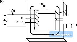
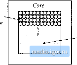
Строительный блокнот Introduction to electronics  Cross-sectional area A, Air gap ЛЛг- Fig. 14,4 Filter mductor (a) assumed geometry, ib) magnetit- tirt-uit. It is assumed that the inductor geometry is topologically equivalent to Fig. 14.4(a). An equivalent magnetic circuit is illustrated in Fig. 14.4(b). The core reluctance and air gap reluctance are (r,A, . - Jl (142) where t, is the core magnetic path length, A, is the core cross-sectional area, is the core permeability, and is the air gap length. Il is assumed that the core and air gap have the same cross-sectional areas. Solution of Fig. 14.4(b) yields т = Ф(.?,-(-.5,) (M-3) Usually, .,and hence Eq. (14.3) can be approximated as ni<b.g (W-t) The air gap dominates the inductor properties. Four design constraints now can be identified. 14.1,1 Maximum Flux Detislty Given a peak winding current l , it is desired to operate the core flux density at a maximum value Д, п. The value of i is chosen to be less than the worst-case saturation flux density В, , of the core tnaterial. Substitution о1Ф =BA, into Eq. (14.4) leads to ni = BA,. Upon letting / = and В = B, we obtain (14.5) (14.6) This is the first design constraint. The turns ratio it and the air gap length £ are unknowns. 14 Л.2 Inductance The given inductance value L must be obtained. The inductance is equal to (14.7) This is the second design constraint. The turns ratio is, core area A., and gap length £ are unknown. 14.1.3 Winding Area As illustrated in Fig. 14,5, the winding must fit through the window, i.e., the hole in the center tif the core. The cross-sectional area of the ctmdnctor, or bare area, is A If the winding has?! turns, then the area of ctipper conductor in the window is iiAu (I4. ) If the core has window area W., then we can express the area available for the winding conducttws as (14.9) where is the window utilization factor, or fill factor. Hence, the third desigu constraint can be expressed as (14.10) Tlte fill factor is the fraction of the core window area that is filled with copper. must lie between zero and one. As di.scussed in [1], there are several mechanism that cause K, to he less than unity. Round wire does not pack perfectly; this reduces K by a factor of 0.7 to 0.55, depending on the winding technique. The wire has insulation; the ratio of wire conductor atea to total wire area varies from approximately 0.95 to 0.65, depending on the wire size and type of insulation. The bobbin u.ses some of the window area. Insulation may be required between windings and/tir winding layers. Typical values of for cores with winding bobbins are: 0.5 for a simple iow-vtiltage inductor, 0.25 to О.Л for an off-line transformer, 0.05 to 0.2 for a high-voltage transformer supplying several kV, and 0.65 for a low-voltage foil transformer or inductor. Wire bare area A  Core window area W. Fig, 14,5 The winding [Uust fit in the cote window area. 14.1.4 Winding Resistance The resistance ofthe winding is Л = р (14,11) wliere p is the re.4istivity of the eondiietor material, C is the length of the wire, and A , is the wire bare area. The resistivity of topper at room tempeiature is 1.724- 10 * П-ст. The ietigth ofthe wire comprising ann-turii winding tan be expressed as t = n(MLT) (14.12) where {MLT) is the mean-length-per-tnrn ofthe winding. The mean-leiigth-pet-ttini is a function ofthe core geometry. Substitution ofEq. (14.12) into (14.11) leads to This is the fourth constraint. 14.1.5 The Core Geometrical Constant The four constraints, Eqs. (14.6), (14.7), (14.10), and (14.13), involve thequantities A, W, and MLT, which are functions of the core geometry, the quautities (, , B, , ft L, AT R, and p, which are given specifications or other known quantities, and n. f-, and/1 which are unknowns. Elimination ofthe unltnownsji, (y, and Л, leads to the following equation: >J (14,14) The quantities on the right side of this equation are specifications or other Itnown quantities. The left side of the equation is a function of tlie core geometry alone. It is necessary to choose a core whose geometry satisfies Eq. (14.14). The quantity К <14.15) {MLT) is called the core geometrical constant. It is a figuie-of-merit that describes the effective electrical size of magnetic cotes, in appiitadons where copper loss and maximum flux density are specified. Tables are included in Appendix D that list the values of A, for several standard families of ferrite cores. has dimensions of length to the fifth power. Equatioti (14.14) reveals how the specifications affect the core size. Increasing the inductance or pealt current requires an increase in core size. Increasing the peak flux density allows a decrease in core size, and hence it is advantageous to itse a core material that exhibits a high saturation flux density. .Miowiiig a larger winding resistance R, and hence larger copper loss, leads to a smaller core. Of course. |