
|
| |
|
Строительный блокнот Introduction to electronics rms values of the wlnciitig currents are approximately equal to the dc compouetits: /, = 4 A, /j = 2 A, Therefore, the sura of the rras winding currents, referred to winding 1, is = Л+. = 4.86 A For this design, it is decided to allow 0.75 W of ctipper lo.ss, and to operate the core at a maximum tlux density of 0.25 Tesla. A fill factor of 0.4 is assumed. The required i.s found hy evalitation of Eq. (14.52), as follows: a.724 10- il - cm)(47 pH)(4.86 A)(5.83 A)-* (0,25T)-(0.75W)(0.4) (.1.63,) = 16- lO-\-in A ferrite PQ 20/16 core is selected, which has a of 22.4 ID cm-\ From .Appendix D, the geometrical parameters for this core are: A. - 0.62 cm, = 0.256 cm and MLT -4.4 cm. The air gap is ft)und by evaluatitin t)f Eq. (14.53) as follows: (4л 10-H/m)(47 ЦНК5.83 A) (0.25T)=C0.62 em) = 0.32imn In practice, a slightly longer air gap would be necessary, to allow for the effects of fringing tlux and other nonidealities. The winding 1 turns are found by evaluation of Eq. (14.54): - (47 ЦНХ5.83 A) , (14.65) (0.25 T)(0.62 cm=) = 17.6 turns The winding 2 turns are chosen according to the desired turns ratio: I2\ (14.66) 28 = 7.54 turm The numbers of turns are rounded off to it, = 17 turns, turns (18:8 would be another possible choice). The window area is allocated to the windings according to the fractions from Eq. (14.55): (17X4 A) n./-(I7)(4.86A) * (1457 The wire sizes can therefore be chosen as foilows: и I (17] use AWG #21 (14.68) . = (0.l695)(0.4)(0.256cm) 2 (7) use AWG #24 14.4.2 CCM Flyback Transformer As a second exaraple, let us design the flyback transformer for the cotiverter illustrated in Fig. 14.13. This converter operates with an input voltage of 2(Ю V, and produces an full-load output of 20 V at 5A. The switching frequency is 150 kHz. Lnder these operating conditions, it is desired that the converter operate in the continuous conduction mode, with a magnetizing current ripple equal to 20% of the dc component of magnetizing current. The duty cycle is chosen to be D = 0.4, and the turns ratio is 2 ! ~ 0.15. A copper los.s of 1.5 W is allowed, not including proximity effect los.se.s. To allow room for isolation between the priraary and secondaty windings, a fill factor of ff = 0.3 is assumed. A maximum tlux density of = 0,25 T is used; this value is less than the worst-case saturation flux density of the ferrite core material. By solution ofthe converter using capacitor charge balance, the dc component ofthe magnetizing current can be found to be --1.25 A (14,69) Hence, the magnetizing current ripple should be Mf, = \20%)l = 0.25A (14.70) and the maximum value ofthe magnetizing current is V = m- =1-A (14.71) To obtain this ripple, the magnetizing inductance should be (14.72) = 1.07 mH The rms value of the pritnary winding current is found using Eq. (A.6) of Appendix A, as follows: = 0,796 A (14.73) Fig. 14.13 Flyback transftitmer design example; (a) convener stlic-malic. (b) typical waveforms. 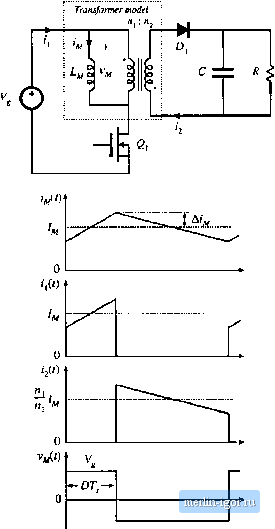 The vnis value of the secondary winding current is found in a similar manner: = fi.50 A (14,74) Note that is not simply equal to the turns ratio muhiplied hy /[, The total rras winding current is equal to: ;, = (, + /3 = 1.77 A (14.75) |