
|
| |
|
Строительный блокнот Introduction to electronics rig, t4.16 Pcteriniiialion of eore loss density for tlic flyback trimsformcr design ejcaiiiple. 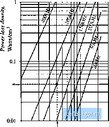 0.04 W/cm 0.01 0.041 0.1 0.3 AB. Tesla 14.5 SUMMARY OF KEY K)INTS 1. A variety of magnetic devices are commonly used in switching converters. These devices differ in their core flux density variations, as well as in the magnitudes of the ac vinding currcnt.s. When the tlux dcitsity variations arc sinall, core lo.s.s can be neglected. Alternatively, a iow-frequency materia] can be used, having higher saturation flux density. 2. The core geometrical constant fi is a measure of the magnetic size of a core, for applications in which topper loss is dominant. In the design method, flux density and total copper loss are specified. Design procedures for single-winding filter inductors and for convendonal multiple-winding transformers are derived. References [2] [3] C. W. T. McLYMAt, Transjoriner and Inductor Design Handbook, Second edition. New York: Marcel Dekker, 1988. S. lit ik, Basics of Switched-Mode Power Conversion: Top()h)gies, Magnetics, and Control, in Advances ill Switclied-Mode Power Conversion, Vol, 2, Irvine: Teslaco, pp. 292-305, 1983. T. G. WILSON JR., T. G. Wilson, and H. A. Owen. Coapling of Magnetic Design Choices lo DC-to-DC Converter Electrical Performance, IEEE Applied Power Electronics Conference, 1994 Record, pp. 340-347. .S.iuKand R. D. MtDDLEBROOK, Coupled-lndtictor and Other Extensions of a New Optimum Topology Switching DC-lo-DC Converter, IEEE Industry- Applications Society Annual Meeting, 1977 Proceedings, pp. 1110-1122. Pmhlenix 5ЙЗ [5] S. Cnit and Z. ZHAI4G, Coupled-Inductor Analysis and Design, IEEE Power Electronics Specialists Conference. 1986 Record, pp, 655-665, [q E, Hnatek, Design of Solid-State Power Supplies, Second edition. New York: Van Nostrand Reinhold, 1981, Chapter 4. Problems 14.1 A simple buck converter operates with a 50 kHi ::witching freijuency and a dc inptit voltage of = 40 V. The oulptit voltage is V = 20 V. The load re:,islance i?, Д > 4 Q. (a) Determine the valtie of Ihe output filler inductance L such that the peak-to-average inductor car-rent ripple Aiis 10* of the dc component /. (b) Determine the peak steady-state inductor citrrenl (c) Design an induclor which has the values off, and from parts (a.) and (b), Use a ferrite EE core, with B = 0.23T. Chotise a value ol winding resistance such that the inductor copper loss is less than or eijtial to 1 W al пютя lemperalure. Assume A, = 0.5. Specify: core size, gap length, wire size (AWG), and number oi turns. 14.2 A bimst converter operates at the following quiescent point: = 28 V, V = 4S V, j°, , = ISO W, ./j. = 100 kHi. Design the inductor for Ihis converter. Choose the inductance value such lhai Ihe peak ttir-renl ripple is 10% ofthe dc induclor ctirrenl. Use a peak fluft density of 0.225 T, and assume a [ill factor of 0.5. Allow copper loss equal lo 0.5% of the load power, al room temperature. Use a ferrite PQ core. Specify: core si/*, air gap length, wire gauge, and number of turns. 14.3 Extension of Ihe approach to design of Iwo-winding transformers. It is desired to design a transformer having a turns ratio of The transformer stores negligible energy, no air gap is required, and the ratio ofthe winding currents iUyijil) h essenlially equal to the turns ratio !r. The applied primary volt-seconds X are defined for a typical PWM voltage wavelorm i,(r} in Fig. 13.45(b): these volt-seconds shotild cause Ihe maximum ftux density to he equal lo a specilied value B - AB, You may assume that the flux density fi(r} contains no dc bias, as in Fig. 13.46. You should allocate half of the cove window area to each winding. The total copper loss Pi also specilied. You may neglect proximity losses. (a) Derive a translormer design procedure, in which the lollowing quantities are specified: total copper loss Pjjj, maximum llnx density Л ; fill factor /f ,wire resistivity p, rms primary current / applied primary volt-seconds X, iind turns ratio \:n, Yt>ur prxKedtire should yield the following data: required core geometrical constant K, primary and secondary turns *i[ and я and primary and secondary wire areas Л,., Ш11Л2- (b) The vohage wavelorm applied tu the transformer primary winding ipf ihe tuk converler [Fig. h.4f(c}] is eijual to the converler input voltage while Ihe transistor conducts, and is equal lo -VD/(1 - D) while the dicde conducts. This converler operates with a switching frequency of 100 kHz, and a transistor duty cycle D equal to 0.4. The dc inpul voltage is V, - 120 V, the dc output voltage is V= 24 V, and the load power is 2ClO W. You may assume a fill factor of A = 0,3, Use yuur procedure of part (a) to design a transformer for this applicatitm, in which ,N,ti = -lT * and P, = 0.25 W at lOtTC. Use a ferrite PQ core. Specify: core size, primary and secondary turns, and wire gauges. 14.4 Coupled induclor design. The two-output forward cunvener ot Fig. 13.47(a) employs secondary-side coupled inductors. An air gap is employed. Design a coupled induclor for the following apphcation: Vj = 5 V, = 15 V, 1 = 20 A, = 4 A, D - 0.4. The magnetizing inductance shijnld be eijual lo 8 дН, referred lo Ihe 5 V winding. Yiju may assume a fill factor ft otO.5. Allow a total of 1 W of copper loss at ifXfC, and use a peak flux density of = 0.2 Т. Use a ferrile EE core. Specify: core size, air gap lenglti, number uflurns and wire gauge for each winding. 14.S Flyback transformer design. A flyback ctmverler operates wilh a 160 Vdc inpLil, and prndtices a 28 Vdc oulpui. The raasimum luad current is 2 A. The iransformer turns ratio is 8:1. The switching frecjnency is 100 kHz. The convener should be designed lo operate in the discontinuous conduction mode at all load currents. The total copper loss should be les.s lhan 0.75 W. (a) Choose the value of transformer magnetizing inductance f, such thai, at maximtim load current, 0 = 0.1 (lhe duly cycle of subinterval ji, in which all semicondticUirs are off). Please indicate wheiher your value of is referred to the primary or secondary winding, What is the peak tran-sisU)r current? The peak diode current? (b) Design a flyback transformer for this application. Use a ferrite pot core wilh = 0.25 Tesla. and wilh fill factor - 0.4. Specify: core size, primary and secondary turns and wire sizes, and ail gap length. (c) For your design of pari (h), compute lhe copper losses in the primary and secondary windings. You may neglect proximity loss. (d) For yoar design uf part [b), compute the core loss. Loss data for lhe core material is given by Fig. 13.20. Is the core loss less than the topper loss computed in Part (t)? |