
|
| |
|
Строительный блокнот Introduction to electronics Transformer Design In the design methods ot the pievious ehaptei, eoppei loss P and maximumfluxdensity l aie specified, while coie loss Pj is not speeifieally addressed. This appiuach is appropriate for a number of applications, such as the filter inductor in which the dominant design cunstraints ;ire copper loss and saturation flux density. However, in a substantial class of applications, the operating flux density is limited by core loss rather than saturation. Ftjr example, in a conventional high-frequency transformer, it is usually песе.ч.чагу to limit the core lo.ss by operating at a reduced value ofthe peak acfluxdensity AB, This chapter covers the generid tratisformer design probletn. It is desired to design a i:-witiding transfortner as illustrated in Fig. 15.1. Both copper loss atid core loss Pj ate tnodeletl. As the operating flux density is increased (by decreasing the number of turns), the copper loss is decreased but the core loss is increased. We will detertnitie the operating tlux density that minitnizes the total power loss It is possible to generalize the core geotnetrical constiuit design tnethod, detfved in the previous chapter, to treat the design of tnagnetic devices when both copper loss and core loss are significant. This leads to the geotnetticid ct)nst;int K, a measure of the effective tnagtietic size of core in a b;ms-tbrtner design application. Several exatnple s of transformer designs via the K tnethod are given in this chapter. A similar procedtue is idso detfved, for design of single-winding inductors in which cote loss is significant. 15.1 TRANSFORMER DESKJN: BASIC CONSTRAINTS As in the ciLse of the filter inductor design, we can write several basic constraining equations. These equatiotis ciin then be combined into a sitigle equation for selection of the core size. In the case of transfortner design, the basic constraints describe the core loss, tlux density, ctjpper loss, and total power loss v,(f) 1 ЛЛг- 2 J. ЛЛг- Fig, 15,1 A t-winding transformer, in wliitli hmtii cort loss und copper loss ure signKiciiiU. vs. fltix density. The tlux density is then cliosen to optimize the total power loss. 15.1.1 Core Loss As described in Chapter 13, the total core loss depends on the peak ac flux density AS, the operating frequency /, and the volume of the core. At a given frequency, we can approximate the core loss by a function of the form (15.1} Again, A, is the core cross-sectional area, ( , is the core mean magnetic path length, and hence A.f is the volume of the core. K is a constant of proportionality which depends on the operating frequency. The exponent P is determined from the core manufacturer.s published data, Typically, the value of pfor ferrite power materials is approximately 2.t); for trther core materials, this exponent hes in the range 2 to 3. Equation (15.1) generally assumes that the applied waveforms are .sinusoidal; effects of waveform harmonic content are ignored here. 15.1.2 Flux Densitv An arbitrary periodic primary voltage waveform Vi(r) i.s illustrated in Fig. 15.2. The volt-.second.s applied during the positive portion of the waveform is denoted \ : 1= (0л (15.2) These volt-seconds, or flux-linkages, cau.se the flux density to change from its negative peak to its positive peak value. Hence, from Faradays law, the peak value of the ac component of the Пчх density is 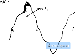 Fig. 1S,2 An arbitrary :i-anst ormcr primary voltage wavcforiiiSi, iilii.tratiiig the volt-second.-? sipfilicti during Ihe positive portion of tlie cycle. 4Й = In Л,. (15.3) Note that, for agiven applied voltage waveform and л we can reduce h£ by increasing the primary turns n,. This has the effect of decreasing the core loss according to Eq. (15.1). However, it also causes the copper loss to increase, since the new windings will be cotnprised of more turns of stnaller wire. As a re.sult, there is an optimal choice for ДВ, in which the total loss is tniniraized. In the nest sections, we will determine the optimal AS, Having done so, we can then tise Eq. (15.3) to determine the primary turns j, as follows: (15.4) It should also be noted that, in sotne converter topologies such as the forward converter with conventional reset winding, the flux density B(() and the magnetizing current i(r) are not allowed to be negative. In consequence, the instantaneous tltix density S(r) contains a dc bias. Provided that the core does not approach sattiration, this dc bias does not significantly affect the core loss: core loss is determined by the ac coinponent of B(r). Equations (15.2) to (15.4) continue to apply to this case, since ДВ is the pealc value ofthe ac ctmiponent of B(r). 15.1,3 Copper Loss As shown in Section 14.3.1, the total copper loss is minimized when the core window area Wj is allocated to the various windings according to their relative apparent powers. The total copper loss is then given by Eq. (14.34). This equation can be expressed in the form (15.5) where |