
|
| |
|
Строительный блокнот Introduction to electronics by Eq. (15.24) as Л.УУл (0.396)(Q.25)(I.78) ,. ,-1 , -;=-722)- =ф AWG #19 аД, (0.20ед0.25)(1.78) .,....., AWG #8 O,.Vy,ja094K5KUS),3,, =>AWGttlfi It may be preferable to wind the 15 V outputs jsing two #19 wires in parallel; this would lead to the same area Ajhut wotild be easier to wind. The 5 V windings eould be wound tising many turns of smaller paralleled wires, but it would pnibably be easier to use a fiat topper foil winding. If insulation requirements allow, proximity losses could be minimized by interleaving several thin layers of foil with the primary winding. 15.4 AC INDLCTOR DESKJN The transformer design procedure of the previous sections can be adapted to handle the design of other magnetic devices in which both core loss and copper ioss are significant. A procedure is outlined here for design of single-winding inductors whose wavefonns contain significant high-frequency ac components (Fig. 15.10). An optitnal value of is found, which ieads to minimum total core-pius-copper ioss. The major difference is that we must design to obtain a given inductance, using a core with an air gap. The constraints and a step-by-step procedure are briefly outlined below. 15.4.1 Outline of Derivation As in the filter inductor design procedure of the previous chapter, the desired inductance L must be obtained, given by t = (13.53) The applied voltage waveform and the peak ac component of the tlux density AB are related according to The copper loss is given by ., ,.P ;(.p/: (15.55) where / is the rms value of/(f). The core loss Pj is given by Eq. (15.1). !5.4 AC Ыисюг Design s81 Window area Core nnean length per turn {MLT) v(t) turns Wire resistivity p Fill factor К Core Core area Air gap <e) 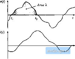 Fig. IS.ie Ac inductor, in which copper los.4 and core loss are significant: (a) definition of terminal quantities, (b)core geometry, (c) arbitrary terminal waveforms. The value of ДД that minimizes the total power loss Я, = P + Pj.is found iu a tnanner si tniiar to the transfortner design derivation. Equation (15.54) is used to eiitnitiate n frotn the expression for P , The optimal AB is then computed by setting the derivative of P, to zero. The result is П 1 w.axw; (15.56) which is essentially the siune as Eq. (15.13). The total power loss P, , is evaluated at this value of AB, atid the resulting expression is manipulated to find K, Tlie result is 2K [PjM where K. is defined as in Eq. (15.16). A core that satisfies this inequality is selected. 15.4.2 Step-by-step AC Inductor Design Procedure The units of Section 15.2 iire emplt;iyed iiere, L Determine core size. (15.5S) Choose a core that is large enough to satisfy this inequality. If necessary, it may be possible to use a smaller core by choosing a core material having lower loss, that is, smaller K,. 2. Evaluate peak ac flux density. (MLT) i (1.5.50) 3. Number of turns. (15.60) 4. Air gap length. (15.61) with Aj.specified in cmand f,expressed in meters. Alternatively, the air gap can be indirectly expressed viaA(mH/l()(X) turns): (15.62) 5. Check for saturation. If the inductorcurrent contains a dc component / ., then the maximum total flux density B , is greater than the peak ac flux density ДД. The maximum total flux density, in Tesla, is given by /lA,. (15,63) If is close to or greater than the saturation flux density S then the core may saturate. The filter inductor design procedure of the previous chapter should then be used, to operate at a lower flux density. 6. Evabtate wire size. |