
|
| |
|
Строительный блокнот Introduction to electronics A winding geometry can now be detertnined, and copper losses due to the proximity effect can be evaluated. If these losses are significant, it may be desirable to further tiptimize the design by reiterating the above steps, accounting for proxiinity losses by increasing the effective wire resisfivity to the value Pef!= (cJcJP(i,:-! where Pj. is the actual copper loss including proximity effects, and P,, is the copper loss predicted when the piDxtmity effect is ignored. 7. Check power loss. 15.5 suiviiviary In a multiple-winding transformer, the iow-freqttency copper lo.sses are minimized whe!i the available window area is allocated to the windings according to their apparent powers, or ampere-turns. .As peak ac tittx density is increased, core loss increases while copper losses decrease. There is an optimum tlttx density that leads to ininimum total power los.s. Provided lhat ihe core material is opei-aied near its imeuded frequency, then the optinntm flux density is less than the saturation flux density. Minimization of total loss then deiermines the choice of peak ac tlttx density. The core geometrica] constant ft is a measure of the magnetic size of a core, for applications in which core loss is significant. In the K design method, ihe peak tlux density is optimized to yield rninimum total loss, as opposed io ihe К design method where peak tlttx density is agiven specification refere14ces [IJ W. J. Gu and R. Lilt, A Study of Volume and Weight vs. Fi-eqttency for High-Frequency Ti-.tnsformers, IEEE Power Electronic.! Specialim. Conference. 1993 Record, pp, 1123-1129. [2J K. d. T. Ngo, R. p. Alley, A. j. Yerman, R. j. Charles, and m. H. Kuo, Evaluation of Trade-Offs in Transfoimer Design for Very-Low-Voliage Power Sttpply with Very High Efficiency and Power Density, IEEE Applied Power Elearonics Conference. 1990 Record, pp. 344-353. [3] A. F, Goldberg and M. F, SciiLECitr, The Relationship Between Size and Power Dissipation in a 1- lOMHz Transfonner. IEEE Power Electronics Specicilist.i Conference, I9S9 Record, pp. 625-634. [4] K. D. T. Ngo and R. S. L.M, Effect of Height on Power Density in High-Frequency Transformers. IEEE Power Electronic! Sfeciolist.! Confereiice, 1991 Recoid, pp. 6tS7-672. [5] R. Б. Ridley and F. C. Lee, Practical Nonlinear Design Optimization Tool for Power Converter Compo- nents, IEEE Power Electronic; Speciesliats Conference. 19K7 Record, pp. 314-323. [6] R. С WoNO, H. A. Owen, and T. G. Wilson, Parametric Study of Minimum Converter Loss in an Energy-Storage Dc-to-Dc Converter, IEEE Power Electronic; Upeciali.M Conference, i9S2 Recoid, pp. 411-425. Problems IS.l Forward converter inJuotor and IranKformer design. The objecnve of itiis probiem set is lo design lhe magnetics (two inductors and one transformer) of the two-transistor, two-output forward converter shown in Fig. 15.11. The ferrite core material to be used for all three devices has a saturation fltix density of approximately 0.3 T al 120C. To provide a safety margin for your designs, you shtitdJ use a maximum flux density B . that is no greater lhan 75% of this value. The core loss at 1(Ю kHz is described by Eq. (15.1), with lhe parameter values [3 =2.6 and K = 50 cm. Caktilate topper loss al ШС. Sieudy-stim conveiter analysis and design. Ytm may assume 100% efficiency and ideal lossless components for this section, (a) Select the transformer turns rados so lhal the desired outpui voltages are obtained when lhe duly cycle is D = 0.4. (b) Specify values ofi, and/.j stich that their current ripples ir, and Aij are 10% of their respective full-load currenl dc components I, and fj, (t) Determine lhe peat and mis currents in each inductor and transformer winding. Inductor design. Allow copper loss of 1 W in Ly and 0,4 W in /,3, Assume a fill factor of/f = 0,5. Use ferrile EE tores-tables of geometrical data for standard EE core sizes are given in Appendix D, Design die output fdter inductors and Z. For each inductor, specify: {/) EE tore size (ii) Air gap length (iVi) Number of turns (/v) AWG wire size Tramfornter design. Allow a total power loss of 1 W, Assume a fill factor of = 0.35 (lower lhan tor lhe filter inductors, to allow spate for insulation between the windings). Use a ferrite EE tore. You may neglect losses due to the skin and proximity effects, but you should include core and copper losses. Design lhe transformer, and specify the following: {;) EE core size (11) turns tt, /ij, and rtj 325 V I ol turns о = 100 kHz 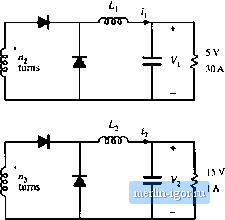 Fig. 15,11 Twu-outputforwardcot)verlerof Problem 15.1, Frobkms 585 (in) AWG wire size for liie three windings ChcLlt yuur transformer design: (iv) Corapttte [he muximum flux density. Will [he tore saltirale? (v) Compote the core loss, the copper loss of each winding, and the total power loss 15.2 A single-trandstor forward converter operates with an input voltage - 160 V, and stipplies two outputs: 24 V al 2 A, and 15 V at й A. The duly cycle is /> = 0.4. The turns ratio between the primary winding and the reset winding is 1:1. The switching freqtiency is 100 kHz. The core material k)ss eqtiatitm parameters are P = 2,7, A = 50. You may assume a fill factor of 0.25. Donotallow the core maximum Ilux density to exceed 0.3 T. Design a transformer for this application, having a total power loss no greater than 1.5 W al lOOC. Neglect proximity losses. Yon may neglect the reset winding. Use a ferrite PQ core. Specify: core size, peak ac flux density, wire sizes, and number of ttirns for each winding. Compute the core and copper losses for ytJur design. 15.3 Flyback/SEPIC transformer design. The transformer ofthe flyback and .SEPIC converters is an energy storage device, which might be more acctirateiy desciibed as a multiple-winding indtictor. The magnetizing indtictance functions as an energy-transferring inductor of the converler, and therefore the transformer normally contains an air gap. The converter may be designed to operate in either the continuous or discondnuous condticlion mode. Core loss may be significant. Il is also important to ensure that [he peak current in the magnetizing inductance doeu not canse saturation. A flyback transformer is tu be designed for the following twc-CLilput flyback cunvertef applicadon; Input: 160 Vdc Output i: 5 Vdc at 10 A Ouiput 2: 15 Vdc all A Switching frequency: lOOkHz Magnetizing indtictance L: 1.33 mH, referred lo primary Tarns rado: 160:5:15 Transformer power loss: Allow 1 W total (a) Does the converter operate in CCM or DCM? Referred to the primary winding, how large are 0 ) the magnedzing current ripple Ai, ( ) the magnetizing current dc component /, and (iii) the peak magnetizing Current /j? (b) Determine (/) the rms winding ctirrents, and ( ) the applied primary voU-seconds J-j. Is J., pru-purtionai to fjjj? (c) Modify the transformer and ac inductor design procedures of this chapter, lo derive a general procedure for designing flyback transformers that explicitly accounts for both core and copper loss, and that employs the optimum ac flux density that minimizes the total loss. (d) Give a gener.il step-by-step design procedure, with all specificatitms and units tleiuly staled. (e) Design the flyback transformer for the converter of part (a), tising yotir step-by-step procedure of part (d). Use a ferrite EE tore, with P = 2.7 and K = 50 W/Tcm, Specify: core size, air gap length, tarn.4, and wire sizes for all windings. (f) For your final design uf part (e), what are (f) the core loss, (ii) the tutal copper loss, and (iri) the peak flax density? |