
|
| |
|
Строительный блокнот Introduction to electronics Power and Harmonics in Nonsinusoidal Systems Recdficalton used to be a much simpler topic. A textbook could cover the topic sitnply by discussing the various circuits, such as the peak-detection and inductor-input rectifiers, the phase-controlled bridge, polyphase transformercumiectioiis, and perhaps mtiitipiiercirctiits. But recently, rectifiers have becotne much mtffe sophisticated, and are n[)W systetns rather than tnere circuits. They often include pulse-width modulated converters such as the boost converter, with cotitrol systems that regulate the ac input current wavefortn. So modern rectifier technology now incoфorates many ofthe dc-dc converter fundntnentals. The reason for this is the undesirable ac line current harmonics, and low power factors, of ctm-ventionai peak-detection and phase-controlled rectifiers. The adverse effects of power system harmonics are well rectignized. These effects include: unsafe neutral current magnitudes in three-phase systems, heating and reduction of life in transfonners atid itidiiction motors, degradation of systetn voltage waveforms, unsafe currents in power-factor-correction capacitors, and malfunctioning of certain power system protectitm elements. In a real sense, conventional rectifiers iire hartnonic polluters of the ac power distribution system. Wilh the widespread deployment of electronic equipment in our stH;iety, rectifier harmonics have bectitne a significant and measurable problem. Thus there is a need for Iiigb-t/ualhy rectifiers, which operate with high power factor, high efficiency, and reduced generation of harmonics. Several international standards now exist that specifically limit the magnitudes of hartnonic currents, tor both high-power equipment such as industrial motor drives, and low-power equipment such as electronic ballasts for fiuorescent lamps and power supplies for office equipment. This chapter treats the П[) of energy in power systems containing nonsinusoidal waveforms. Average power, rms values, and power factor are expressed in terms of the Fourier series of the voltage and current wavefortns. Harmonic currents in three-phase systems are discussed, and present-day standards are listed. The fidlowing chapters treat harmonics and harmonic mitigation in conventional iine-conimutated rectifiers, high-quality rectifiercircuits and their models, and control of high-quality rectifiers. 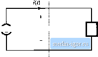 Source f+ 1 40 I Load Surface S Fig. 16.1 Observe (lie traiismi.skiioi! of energy throiigb surface S. 16.1 AVERAGE POWER Let lis consider the transmission of energy from a source to a load, through a given surface as in Fig. 16.1. In the network of Fig. 16.1, the vtdtage waveform v(r) (not necessarily sinusoidal) is given by the source, and the current waveform is determined by the response of the load. In the more general case in which the source output impedance is significant, then v{l) and iff) both depend on the characteristics of the source and load. Balanced three-phase systems may be treated in the same manner, on a per-phase basis, using a line cunent and line-to-neutral voltage. If i-(r) and ((f) are periodic, then they may be expressed as Fourier series: iW = / -! Ё / cos[nca(-0 ) (16,1) where the period of the ac line voltage waveform is defined as Г= 2n!(il. In general, the instantaneous power p(l) - v(t)i(t) can assume both positive and negative vahies at various points during the ac line cycle. Energy then flows in both directions between the source and load. It is of interest to determine the net energy transmitted to the load over one cycle, or Hnmdt This is directly related to the average power as follows: P... = - (16.2) (16,3) Let tis investigate the relationship between the harmonic content of the voltage and cunent waveforms, and the average power Substitution of the Fourier series, Eq. (16.1), into Eq. (16.3) yields (16,4) To evaluate this integral, we must multiply out the infinite series. It can be shown that the integrals of cross-produtt terms are zero, and the only eontrlbutions to the integral cotnes from the products of voltage and ctirrent harmonics of the same frequency: J I V COS - ф ) i , cos [rfjOJl - e ,) The average power is therefore dl = 0 if fi III COs((p -e ) jfi!- (1Й.5) (16.6) So net energy is transmitted to the load only when the Fourier series of v{t) and i{t) contain terms at the same freqtiency. For example, if v{t) and !(f) both contain third harmonic, then net energy is transmitted at the third harmonic frequency, with average power etjual to cos[ф,-0,] (lfi.7j Here, 1-5/3/2 is equal to the rms volt-amperes of the third harmonic current and voltage. The cos (ф-, - 9-,) term is a ilisplacement term which accounts for the phase difference between the third harmonic voltage and current. Some examples of power flow in systems containing harmonics are illustrated in Figs. 16.2 to 16.4. In exaraple 1, Fig. 16.2, the voltage contains fundamental only, while the current contains third har- 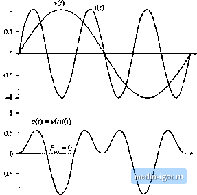 -1 -I Fig. 1(1.2 Voltage, current, and insiaiiturieous power waveforms, example l.The voltage contains only fundameu-tai, and tiie cuirent coniains oidy third harmonic, flie average power is zero. |