 | |
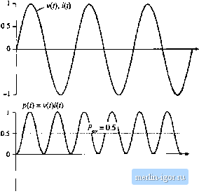
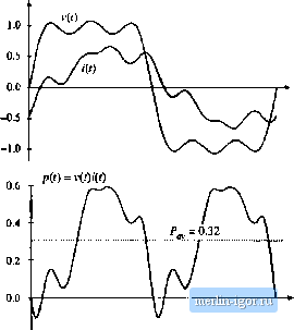
Строительный блокнот Introduction to electronics  -0.5 - Fig, 16.3 Voltage, Сштет, und instantaneous power waveforms, example 2. The voltage utid etirreitt eaeli coiitaiit only third hatmonic, und are in phase. Net energy is transmitted at the third liarmonie frequency.  -0.2 Fig. 16.4 Voltage, current, and instantaneous power waveforms, example 3. The voltnge contains fundamental, third, and fitth harmonics, fhe current contaiits fundamental, iifth, and seventh hiirmonics. Net energy is transmitted at the fundamental and fifth harmonic fi-equeiicies. moiiic only. It tan be seen that the instantaneous power waveform p(l) has a zero average value, and henee P is zero. Energy circulates between the .source and load, btit over one cycle the net energy transferred to the load is zero. In example 2, Fig. 16.3, the voltage and current each contain only third har-tnotiic. The average power is given by Eq. (lfi.7) in this case. In example 3, Fig. 16.4, the voltage waveform contains fundamental, third harmonic, and tlfth harmonic, while the current contains fundatnental, fifth harmonic, and seventh hartnonic, as follows: v(t) = 1.2 cos (ш) + 0.33 cos (ЗшО + 0.2 cos (Scof) (16 S) ;(() = 0.6 cos Ш + 30*) + 0, t cos (5w 4- 45 ) + 0.1 cos (Imt + 60°) Average power is transmitted at the futidamentai and fifth hartnonic frequencies, since only these frequencies are present in both waveforms. The average power is found by evaluation ofEq. (16.6); all terms are zero except for the fundamental and fifth harmonic terms, as follows: = ЛШ os (30=) . COS (45=) = 0.32 CI 6.?) The instantaneous power and its average are illustrated iit Fig. 16.4(b). 16.2 ROOT-MEAN-SQUARE (RMS) VALUE OF A WAVEFORM The rms value of a petiodic wavefortn i(f) with peritxi T is defined as (rntsvalufi) = y jl v4i)dt ( 1) The rms value can also be expressed in terms ofthe Fourier componettts. Insertion ofEq. (Ifi.l) into Eq. (16.10), and simplification using Eq. (16.5), yields (mis value) =\/v/J+ 2 C- ) Again, the integrals ofthe cross-product terms are zero. This expression holds when the wavefortn is a current: (rms current) = + Thtis. the presence of harmonics in a waveform always increases its rms vaitie. In particular, in the case where the voltage v(/) contains only fundamental while the current i(/) contains harmonics, then the har-mottics ittcrense the rms value ofthe current while leaving the average power uttchanged. This is undesirable, because the harmonics do not lead to net delivery of energy to the load, yet they increase the ( losses in the system. In a practical system, series resistances always exist in the source, load, attd/or transmission wires, which lead to unwanted power losses obeying the expression (rms turreni)X,ri (16.13) Examples of such loss elements are the resistance of ac generator windings, the resistance of the wire connecting the source and load, the resistance of transformer windings, and the resistance of semiconductor devices and magnetics windings in switching converters. Thus, it is desired to make the rras current as small as possible, while transferring the required araount of energy and average power to the load. Shunt resistances usually also exist, which cause power k)ss according to the relation (rtnsvoltag (16.14) .,Jmjji; Examples include the core losses in transforraers and ac generators, and switching converter transistor switching loss. Therefore, it is desired to alst) raake the rras voitage as small as possible while transferring the required average power to the load. 16.3 POWER FACTOR Power factor is a figure t)f merit that measures ht)W effectively energy is transmitted between a source and load network, it is measured at a given surface as in Fig. 16.1, and is defined as p, f,c:or = (ave. age power) (, Й. 15) (rnis voltage) (rnts currott) The power factor always has a value between zero and one. The ideal case, unity power factor, occurs for a load thatt)beys Ohms Law. In this case, the voltage and current waveforms have the same shape, contain the same harmtinic spectrum, and are in phase, For a given average power throughput, the rras current and voltage are rainimized at tnaxiraum (unity) power factor, that is, with a linear resistive load. In the case where the voltage contains no harmonics but the load is nonlinear and contains dynamics, then the power factor can be expressed as a product of two terms, one resulting from the phase shift of the fundatnental component of the current, and the other resulting from the current harmonics. 16.3.1 Linear Resistive Load, Nonsinusoidai Voltage In this case, the current harmonics are in phase with, and proportional to, the vt)itage harraonics. As a result, all harmonics result in the net transfer of energy to the bad. The current harmonic magnitudes and phases are I (16.16) TTie rms voltage is again and the rms current is 0 = ф so С05(е -ф )= ( (16.17) (rms vohage) = /;7Ё С ) |