
|
| |
|
Строительный блокнот Introduction to electronics circuit liaving nearly unity power factor would allow a significant increase in available dc load power: (ac voltage) (derated bleaker current) (power factor) (rectifierefliciency) = (I20V) ( 0%п(15Л) (0,t)9) (0.93) = 1325 W (16.28) or almost twice the available power of the peak detection rectifier. This alone can be a compelling reason to employ high quality rectifiers in commercial systems. 16.4 POWER PHASORS IN SINUSOIDAL SYSTEMS The apparent power is defined as the product t)f the rms voltage and rms current. Apparent ptmer is easily measured-it is simply the product t)f the readings of a voltmeter and ammeter placed in the circuit at the given surface. Many ptjwer system elements, such as transformers, must be rated according to the apparent power that they are able to supply. The unit of apparent power is the volt-ampere, or VA. The power factor, defined in Eq. (16.15), is die ratio of average power to apparent power, In the case of sinusoidal voltage and current waveforms, we can additionally define the complex power S and the reactive power Q. If the sinusoidal voltage v(f) and current ;(/) can be represented by the phasors V and /, then the complex power is a phast)r defined as S = VI*P + jQ (16.29) Here, /* is the complex conjugate of /, and; is the square root of -1, The magnitude of S, or j S {, is equal to the apparent power, measured in VA. The real part of S is the average power P, having units of watts. The imaginary part of S is the reactive pt)wer Q, having units of reactive volt-amperes, t)r VARs, A phasor diagram illustrating 5, P, and Q, is given in Fig. 16.8. The angle (ф, - 9,) is the angle between the voltage phasor Vand the current phasor/. (ф, - 0)is additionally the phase of the complex power S. The power factor in the purely sinusoidal case is therefore s = vr 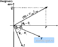 Real axis Fig. 16.8 Power phasor diagram, for a sinusoidal .system, illustrating the voltage, current, mid complex power phasors. power factor = Y = cos (ф I-Oj) (16.30) It should be emphasized that this eqiiatioit is valid oitiy for systems in which the voltage and currettt are purely sintisoidal. The distortion factor of Eq, (16.24) then becomes unity, and the power factor is equal to the displacement factor as in Eq. (16.30). The reactive power Q does nf)t lead to net transmission of energy between the source and load. When reactive power is present, the rms current and apparent power are greater than the minimum amount necessary to transmit the average power P. In an inductor, the current lags the voltage by Qi} , causitig the displacemetit fattt)r ft) be zero. The altetxiate storing atid releasing of energy iti an itiductor leads to current flow and nonzero apparent power, but the average power P is zero. Itist as resistors con-stmie real (average) power P, inductors can be viewed as consutners of reactive power Q. In a capacitor, the current leads to voltage by 90°, again Causing the displacement factor to be zero. Capacitors supply reactive power Q, and are commonly placed in the utility power distribution system near inductive loads. If the reactive power supplied by the capacitor is equal to the reactive power consumed by the inductor, then the net current (flowing from the source into the capacitor-inductive-load cotnbination) will be in phase with the voltage, leading unity power factor and tninitnum rtns current magnitude. It will be seen in the next chapter that phase-controlled rectifiers prtxiuce a nonsinusoidal current waveform whose fundamental component lags the voltage. This lagging current does not arise from energy storage, but it does nonetheless lead to a reduced displacement factor, and tt) rms current and apparent power that are greater than the minimum amount necessary to transmit the average power. 16.5 HARMONIC CURRENTS IN THREE PHASE SYSTEMS The presence of harmonic currents can also lead to sotne special probietns in three-phase systems. In a four-wire tliree-phase system, harmonic currents can lead to large currents in the neutral conductors, which may easily exceed the conductor rms current rating. Power factor correction capacitors may experience significantly increased rms currents, causing them to fail. In this section, these problems are exatn-ined, and the properties of harmonic current flow in three-phase systetns are derived. 16.5.1 Harmonic Currents in Three-Phase Four-Wire Networks Let us consider the three-phase four-wire network of Fig. 16.9. In general, we can express the Fourier series ofthe line curreitts and iine-iteutral voltages as follows: C) = U+2 f.tCos (Aw-9 i) hit) = -1- t cos {Ш1 - 120 ) - e ,) (16-31) i,.(0 = /,<!+£ Lt cos Iktai + 120) -6,) 1= I PvKeranil Hanmiiics in Nonsinusoidai Systems Ideal source 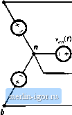 с i,(t) Neutral connection  Nonlinear loads Flfr 16.9 Current flow in a three-phase four-wire network. (0= V cos ((ЙГ) vt (t) = V , cos (tor - 120 ) v ,()= 1 сок(шг + 120°) The neutral current is therefore t = i + ij, +1., or (0 = + /ш + Ло + cos (ftcor - 0 t) + cos (t(a)/- 120°) ~ e) -I-cos (t(<iw - 120) -0) (16.32) (16.33) When the load is unbalanced (even though the voltages are balanced and undistorted), we can say little else about the neutral and line currents. If the load is unhahmced and nonlinear, then the line and neutral currents may contain harmonics of any order, including even and triplen harmonics. Equation (16.33) is considerahiy simplified in the case where the loads are balanced. A hai-anced nonlinear load is one in which / - lbt = ik ~ h ak ~ ьк ~ ck ~ tnonics of the three phases all have equal amplitudes and phase shifts. In this case, Eq. (16.33) reduces to iJt) = 3f + 2 3/i cos (ioK - t = ].6.!).- (16.34) Hence, the fundamental and most of the harmonics cancel mu, and do not appear in the neutral conductor. Thtis, it is in the interests of the utility to balance their nonlinear loads as well as their harmonics. But not all of the hannonics cancel out of Eq. (16.34): the dc and niplei\ (tripie-u, or 3,6,9,...) harmonics add rather than cancel. The nns neutral current is t=j,6.9.-- z (16.35) Example A balanced nonlinear load produces line currents containing fundamental and 20% third hartnonic: (o (t) = /]cos((of - Oj) -I- 0.2/ cos{3t>)/ - Qj). Find the rms neutral current, and compare its amplitude to the rms line current amplitude. |