
|
| |
|
Строительный блокнот Introduction to electronics 16.5 Harmonic Currents in Three Phase Systems 601 Sol It! ion: (0.21 if 0.6f (16.36) ] + (0.2/.) rT-JTTST I, So the neutral current magnituile is 60% ofthe line current magnituile! The triplen harmonics in the three phases adil, such that 20% third harmonic leads to 60% third harmonic neutral current. Yet the presence of the third harmonic has very little effect on the rms value of the line current. Significant unexpected neutral current flows. 16.5.2 Harmonic Currents in Tliree-Phase Three-Wire Networks If there is no neutral connectitm to the wye-Connected lt>ad, as in Fig. 16.10, then i(() must he zero. If the load is balanced, then Eq. (16.34) still applies, and therefore the dc and triplen harmtmics ofthe load currents must be zero. Therefore, the line currents i and i. canntU contain triplen or dc harmonics. What happens is that a vohage is induced at the load neutral point containing dc and triplen harmonics, which eliminates the triplen and dc load current harmonics. This result is true tmly when the load is balanced. With an unbalanced load, all harmonics can appear in the line currents, including triplen and dc. In practice, the load is never exactiy balanced, ;md some small amtmnts of third harmonic line currents are measured. With a delta-connected load as in Fig. 16.11, there is also no neutral connection, so the line currents cannot contain triplen or dc coinponents. But the loads are connected line-to-line, and are excited by undistorted sinusoidal voltages. Hence triplen harmtmic and dc currents do, in general, flow through the nonlinear loads. Therefore, these currents simply circulate around the delta. If the load is balanced, then again no triplen harmonics appear in the line currents. 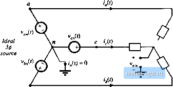 У Nonlinear loads Fig. 16.10 Current How in a three-phase three-wire wye-connected neiwork.  С i,0) (0 = 0 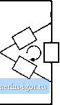 Delta-connected nonlinear loads Fig, 16.11 A balanced nonlinear delta-connected load nray generate rriplen current harmonics. These harmonies circulate around the delta, but do not How through the lines if tlve load is balanced. 16.S.3 Harmonic Current Flow In Power Factor Correction Capacitors Harmonic currents tend to flow througtt shunt-connected power factor correction capacitors. To some extent, this is a good tiling because the capacitors tend to low-pass filter the power system currents, and prevent nonlinear loads from polluting the entire power system. The flow of harmonic currents is then confined to the nonlinear load and local power factor correction capacitors, and voltage waveform distortion is reduced. High-frequeitcy harmonic currents tend to flow through shunt capacitors because the capacitor impedance decreases with frequency, while the inductive impedance of transmission lines increases with frequency. In this sense, power factor correction capacitors mitigate the effects of harmonic currents arising from nonlinear loads in much the same way that they mitigate the effects of reactive currents that arise from inductive loads. But the problem is that the power factor correction capacitors may itot be rated to handle these harmonic currents, and hence there is a danger that the capacitors may overheat and fail when they are exposed to significant harmonic currents. The loss in capacitors is modeled using an equivalent series resistance (esr) as shown in Fig. 16.12. The esr models dielectric loss (hysteresis of the dielectric D-E loop), coittact resistance, aitd foil and lead resistances. Power loss occurs, equal to tiesr). Dielectric materials are typically poor conductors of heat, so a moderate amount of power loss can cause a large temperature rise in the center of the capacitor. In consequence, the rms current must be limited to a safe value. Typical power factor correction capacitors are rated by voltage V, frequency/ and reactive power in kVARs. These ratings are computed from the capacitance С and safe rms current /, assuming undistorted sinusoidal waveforms, as follows: Fig, 16,12 Capacitor equivalent circuit, tosses are iiuideled by an equivalent series resistance (esr). rated nns voltage V , = 2n/C (16.37) 16.6 AC Line Current Harmmtic Standards 603 rated reactive power = (16.38) In an undistorted system, the mis current, and hence also the capacitor esr loss, cannot increase unless the rms voltage is also increased. But high-frequency harmonics can lead to larger rms currents without an increased voltage. Any harmonics that flow result in increased rms current beytmd the expected value predicted by Eq. (16,37). If the capacitor is not rated to handle additional power loss, then failure or premature agin can occur. 16.6 AC LINE CURRENT HARMONIC STANDARDS Besides the increased currents and reduced power factors of peak detection rectifiers, the harmonics themselves can be detrimental: if large enough in magnitude, they can pollute the power system. Harmonic currents cause distortion of the voltage waveform via the power system series impedance. These voltage harmonics can interfere with the operation of nearby loads. As noted previously, increased currents in shunt capacitors, and increased losses in distribution transformers and ac machines, can lead to premature aging and failure of these devices. Odd triplen harmonics (triple-н: 3 *, 9 I5 etc.) lead to unexpectedly large neutral currents in three-phase systems. Harmonic currents can also excite system resonances some distance from their source, wilh results that are difficult to predict. For these reasons, a number of organizations have adopted standards that limit the magnitudes of the harmonic currents that a load is allowed to inject into the ac line. The US military was one ofthe early organi/atitms to recognize these problems; the very strict 3% limit was initially adopted. The standards adopted by the lEC and IEEE are more recent, and are intended for conventional utility systems. A fourth example, not discussed here, is the telephone interference factor, which limits power distributitm system harmonics in cases wheti telephone lines and power lines share the me poles, 16.6.1 International Electrotechnical Comtnission Standard 1000 This international agency adopted a first draft of their lEC 555 standard in 1982. It has since undergone a number of revisions, and has been superceded by lEC lIMM) 7. This standard is now enforced in Europe, making it a de facto standard for commercial equipment intended to be sold worldwide. The lEC l(XX)-3-2 standard covers a number of different types of low power equipment, with differing harmonic limits. It specifically limits harmonics for equipment having an input current of up to 16 A, connected to 50 or 60 H/., 220 V to 240 V single phase circuits (two or three wire), as well as 380 V to 415 V three phase (three or four wire) circuits. In a city environment such as a large building, a large fraction of the total power system load can be nonlinear. For example, a major portion of the electrical load in a building is comprised of fluorescent lights, which present a very nonlinear characteristic to the utility system. A modern office may also contain a large number of personal computers, prititers, copiers, etc., each of which may employ peak detection rectifiers. Although each individual load is a negligible fractitm ofthe total l(x;al load, these loads can collectively iiecome significant. The lEC 1IXXK3-2 standard defines several categories of equipment, each of which is covered by a different set of harmonic limits. As an example. Table 16.1 shows the haimonic limits for Class A equipment, wliich includes low liarmonic rectifiers for computer and other office equipinent. The European norm EN 610(ю-3-2 defines similar limits. |