
|
| |
Строительный блокнот Introduction to electronics 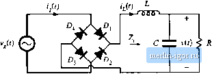 Fig. 17,1 CoEivenitiinal single-phase full-wave leciificr, witli dc-sidc f.-C tiliei cuit of Fig. 17.1. In this application, the L-C filter is required to filter the conducted electromagnetic interference (EMI) generated by the converter. The inductor and capacitor element values are typically small in value, and v(t) is approximately a rectified sinusoid. More generally, there may be several sections of L-C filter networks, connected to both the dc and ac sides of the diode rectifier, which filter EMI, smooth the dc output voltage, and reduce the ac line current harmonics. The presence of any filter degrades the ac current waveform of the rectifier. With no reactive elements (Z, = 0 and С = 0), the rectifier presents a purely resistive load to the ac input. The output voltage v(t) is then a rectified sinusoid, there are no ac line current harmonics, and the power factor is unity. Addition of reactive elements between the rectifier diodes and the load leads in general to ac line current harmonics. Given that such a filter is necessary, one might ask what cati be done to keep these harmotiics as small as possible. In this sectioti, the dependence of the ac line current total harmonic distortion on the filter parameters is described. The circuit of Fig. 17.1 getierates odd harmonics of the ac line voltage in the ac line current. The dc output voltage contains dc and even harmonics of the ac line voitage. The circuit exhibits several modes of operation, depending on the relative values of L, C, and R. It is easiest to understand these modes by considering the limiting cases, as follows. 17,1.1 CunUnuuus CondiicUon Mude When the ittductor L is very large, then the inductorcurrent tii) is essentially constant. This follows from the inductofdefinition vjj) = Lciiij,t)/dt. For a given applied inductor voltage waveform vj,!), the slope dif(f)ldt can be made arbitrarily small by makitig L sufficietitly large. In the limiting са.че where L is infinite, the slope di[(l)/dt becomes zero, and the inductorcurrent is constant dc. To provide a path for the constant inductor to flow, at least two of the rectifier diodes must conduct at any given instant in time. For the circuit of Fig. 17.1, diodes i*, and Dt. conduct when the ac line voltage v(i) is positive, and D and conduct when V(t) is negative. The ac line current waveform is therefore a square wave, with 1(0 = when v(t) \s positive, and = - iit) when vU) is negative. The diode conduction angle p, defined as the angle through which one of the diodes conducts, is equal to 180° in CCM. The rms value of a square wave is equal to its peak value ff., in this case the dc load current. The fundamental component of a square wave is equal to ilJn., The square-wave contains odd harmonics which vary as [lit. The distortion factor is therefore distortion factor = 1: --- = - = 90.0% It fl7.n The total harmonic distortion is
Fig. 17.2 Typical ac line current and voltage vvaveforms, continuous conduction niotie./(,/y -,0,- 0-25. THD = distortion factor (17.2) So the limiting case ofthe large inductor leads to some significant harmonic distortion, although it is not as bad as the pealc detection rectifier case. Since the square wave is in phase with the ac input voltage, the displacement factor is unity, and hence the power factor is equal to the distortion factor. Whenever the inductor is sufficiently large, the rectifier diodes conduct continuously (i.e., there is no time interval in which all fourdiodes are reverse-biased). This is called the continuous conduction mode (CCIVl). A typical ac line current waveform is plotted in Fig. 17.2 for a finite but large value of L It can be seen that the ac line current is discontinuous at the ac line voltage zero crossing, as in the square-wave limiting case. Some ringing is also present. This waveform contains a total harmonic distortion of approximately 29%. 17.1.2 Diseuntinuuus Cunduetion IVIode The opposite са.че occurs when the inductor is very small and the capacitor С is very large. This is the peiik detector ciicuit. En the limit as L goes to zero and С goes to infinity, the ;ic line current appioaches a stringof delta (impulse) functions that coincide with the peaks ofthe sinusoidal input voltage waveform. It can be shown that, in this limiting case, the THD becomes infinite whde the distortion factor and power factor become zero. Of course, in the practical case the current is not infinite; nonetheless, large THD with low power factor is quite possible. The diodes conduct for less than one-half of the ac line period, and hence 3< 180° in DCIVI. Whenever the capacitor is large and the inductor is small, the rectifier tends to peak detect, and the rectifier operates in the discontinuous conduction mode (DCM), There exist time intervals of nonzero length where all four rectifier ditxles are reverse-biased. A typical set of waveforms is plotted in Fig. 17.3, where the capacitor is large but finite, and the inductor is small but nonzero. The ac hne voltage and the value of the load resistance are the same as in Fig. 17.2, yet the peak cunent is substantially larger. The THD for this waveform is 145%, and the distortion factor is 57%. THD = 145% 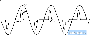 Fig. 17.J Typical ac line current and voltage waveforms, discontinuous conduction mode./j = Я.4, = 121. 17.1.3 Behavior When С is Large A variety of authors have discussed the solution of passive rectifier circuits; several works are listed in the references [8-15]. Analysis of even the simple circuit of Fig. 17.1 is surprisingly complex. R)r the case when С is infinite, it was shown in [8] that the rectifier waveshapes can he expressed as a function of a single dimensionless parameteri, defined as (17,3) where Tj = [ is the ac line period. Equation (17,3) is of the same form as Eq. (5,6), used to define the dimensionless parameter Awhich governs the DCM behavior of PWM converters. Figure 17,4 illustrates the behavior of the single-phase rectifier circuit of Fig. 17.1, as a function of and for infinite С [Щ. When is greater than approximately 0.1, the rectifier operates in CCM, with waveforms similar to those in Fig. 17.2. The voltage conversion ratio M is defined as (17.4) where 1/, is the peak value of the sinusoidal ac input voltage. In CCM, the output voltage is ideally independent of load, with M = 2/n. Addition of ac-side inductance can cause the output voltage to exhibit a dependence on load current. The total harmonic distortion in CCM is nearly constant and equal to the value given by Eq. (17.2). fsear the boundary between CCM and DCM, the fundamental component of the line current significantly lags the line voltage. The displacement factor reaches a minimum value slightly less than 80%, and power factors between 70% and 80% are observed. For 0.1, the rectifier operates heavily in DCM, as a peak-detection rectifier. As K is decreased, the displacement factor approaches unity, while the THD increases rapidly. The power factor is dominated by the distortion factor. The output voltage becomes dependent on the load, and hence the rectifier exhibits a small but nonzero output impedance. For less than approximately 0.05, the waveforms are unchanged when some or all of the inductance is shifted to the ac side of the diode bridge. Figure 17.4 therefore applies to rectifiers contain- |