
|
| |
Строительный блокнот Introduction to electronics 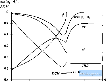 ПЛ The Siuxk-Phase Flitl-Wave Reaifier 613 WO p 200* -Г ISO 150% 135 100 - 90° . - 30% - 45- l 0 Fie, 17-4 Diode conduction angle P, displacement facior, power factor, conversion ratio, and total harmonic distortion ofthe reclifier circuit of Fig, 17.1, with infinite capacitance. ing both ac-side and dc-side inductance, provided that the circuit operates sufficiently deeply in DCIVI. The parameter/l is coinputed according to Eq. (17.3), with L talceii to be the total ac-side plus dc-side inductance. A coininoii example is the case where the circuit contains no physical discrete inductor; the periomiance is then detenniiied by parasitic elements such as the capacittjr equivalent series inductance, the inductance ofthe utility distribution wiring, and transformer leakage inductances. 17.1,4 Minitttiing THD When С is Small Let us ГКШ consider the perfonnance of the second case, in which the inductor and capacitor are small and are intended solely to prevent load-generated EMI from reaching the ac line. En this case, dc-side filtering of the low-frequency even voltage harmonics ofthe ac line frequency is not necessary. The filter can be characterized by a corner frequency/Jj, ch£U £icteristic impedance Яд, and -factor, where / - 1 271VZC (17.5) To obtain good fiitering of tiie EMI, tlie toinei- frequency /j, shouid be selected to be sufficientiy low. However, as can be seen from Eq. (17.5), reducing the value of/q requires increasing the values of £, and/or С As described above, it is undesirable to choose either element value too large, because large distortion results. So, should not be too low, and there is a limit to the amount of fiitering that can be obtained withont significantly distorting the ac line current waveform. How low can he? Once /,) is chosen, how should L and С be chosen such that THD is minimized? We might expect that THD is increased when the phase of the filter input impedance - Z,(/[o), evaluated at the second harmonic of the line frequency or 2/7 differs significantly from (P. When the zero crossings of the voltage and current waveforms do not coincide, then diode switching distorts the current waveform. To a lesser extent, input impedance phase shift at the higher-order even harmonic frequencies of the ac line frequency should also affect the THD. The input impedance Z/is) contains two zeroes at frequency/ and a pole at frequency f, -flQ- To obtain small phase shift at low frequency,/ must be sufficiently large. In addition, Q must be neither tot) sinall nor too large: small Q causes the zeroes at,/j, to introduce low-frequency phase shift, while large 2 causes the pole at f, to occur at low frequency. An approximate plot of THD vs. the choice olXaiid Q is given in Fig. 17.5. It can be seen that there is an optimum choice for Q: minimum THD occurs when Q lies in the range 0.5 to 1. A typical waveform 1.ч plotted for the choice/ц ; = 10, 2 = 1, in Fig. 17.Й. The THD for this waveform is 3.6%, and the distortion factor is 99.97%. Sinall Q corresponds to CCM operation, with huge L aud sinall С In the extreme case as Q 0, the ac line current tends to a square wave with THD = 48%. Large Q corresponds to DCM operation, with small L and large C. In the extreme case as Q , the ac line current tends to a string of delta functionswith TlID > The optimum choice of Q leads to operation near the CCM-DCM boundary, such that the ac line current waveform contains neither step changes nor subintervals of zero current. In the case when the load resistance R varies over a wide range of values, it may be difficult to opdmize the circuit such that low THD is always obtained. It can he seen that increasing fjfi ieads to low THD for a wider range of load resistance. Ftjr example, when fg = .5/ THD < 10% can be obtained only for Q between approximately 0.6 and 1,5, which is a 2.5:1 range of load resistance variations. If the THi>=io% 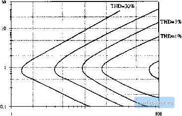 THD=0.5% Kig, 17.5 Approximate total harmonic distortion of the sitigle-phaso diode leciifier with dc-side lC lilter
Iig. 17,6 Typical ac line currem and vohage wavefonns. near the boundary between coutinaous and discontinuous modes and with small dc filter capacittjr.= 10, у = 1. fiher cutoff frequency /ц is increased to 20/, then THD < 10% is obtained for Q between approximately 0.15 and 7, or nearly a 50:1 range of resistance variations. In most cases, maximum harmonic limits are enforced only at full load, and hence it is possible to design with relatively low values of/oZ/if desired. 17.2 THE THREE-PHASE BRIDGE RECTIFIER Abasic full-wave three-phase uncontrolled rectifier with LC output filteris shown in Fig. 17.7, Itsbehav-ior is simiiar to the single-phase case, in that it exhibits both continuous and discontinuous conduction modes, depending on the values of L and C. The rectifier generates odd non-triplen harmonics in the ac line current. So the ac line current may contain 1, 5*, 7* , Ll , 13, etc. harmonics. The dc output may contain dc and even triplen harmonics: 0, 6, 12, 18, etc. In the basic circuit of Fig, 17.7, no more than two of the six diodes can conduct during each interval, and hence the line current waveforms must contain intervals of nonzero length during which the current is zero. Unlike the single-phase case, the ac hne current waveforin must contain distortion even when the filter elements are removed. 17.2.1 Continuous Cunductiun IVIode In the continuous conduction mode, each ac line current is nonzero for 120 degrees out of each line half-cycle. For the remaining 60 degrees, the current is zero. This mode occurs when the inductance L is sul- ac **i
de load Fig, 17.7 Basic iincotdndlcd 30 bridjje rectifier circuit, witJi de-.side L С filler, |
|||||||||||||||||||||||||||||||||||||||||||||