
|
| |
Строительный блокнот Introduction to electronics 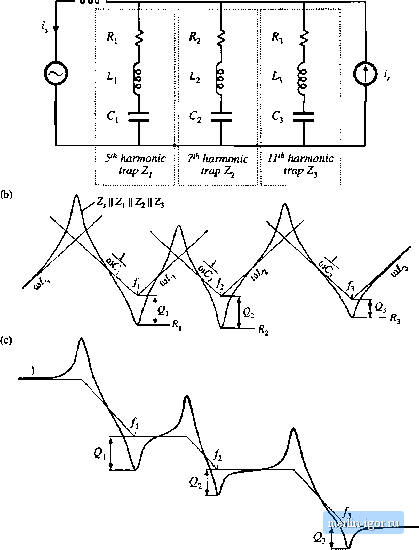 Fig, n.22 Construction of approxiniate frequency response for a harmonic trap filter that attenuates the fifth, seventh, and eleventh harmonics: (a) impedance asymptotes, (b) transfer function asymptotes. ply the resonant frequency ofthe shunt impedance Z or r mi 1 2n 2nL,C, (17.15) ]n addition, care must be exercised regarding the parallel resonance, Since no three-phase system is exactly balanced, small amounts of third harmonic currents always occur These currents usually have negligible effect; however, the parallel resonance of the harmonic trap filter can increase their magnitudes significantly. Even worse, the Q-factor of the parallel resonance, Q is greater than the series-resonance Q-factor Q, The filter circuit of Fig. 17.20 is simple enough that an exact analysis can be performed easily. The exact transfer function is (17.16) where 2л 2k/l;c; >l> 2 2ж./11;7Цс; R, V с, The resonant zeroes do indeed appear at the series resonant frequency, while the parallel resonance and its associated resonant poles appear at frequency/, determined by the series combination of L, and L,. To attenuate several harmonics-for example, the fifth, seventh, and eleventh-series resonant networks can be tuned to provide resonant zeroes at each. A circuit is given in Fig. 17.22(a), with the impedance asymptotes of Fig, 17.22(b). The resulting approximate H{s) \\ is given in Fig. 17.22(c). It can be seen that, associated with each series resonance is a parallel resonance. Each parallel restinant frequency should tie chosen such that it is not significiuitly excited by harmonics present in the network. The filter transfer function can be given high-frequency single-pole roUoff by addition of a bypass resistor Л;, as illustrated in Fig. 17.23(a). Typical impedance and transferfunction asymptotes for this network are constructed in Fig. 17.24. The bypass resistor allows some additional attenuation of the higher-order harmonics, without need for series resonant traps tuned to each harmonic. The network of Fig. 17.23(a) is sometimes called a high pass network, because it allows high-frequency currents to flow through the shunt branch. But it causes the overall filter transfer function H{s) to reject high frequencies. A simple harmonic trap filter that contains series resonances that can be tuned to the fifth and Fig. 17,23 Addition ol bypass resistor R , to a scries resonant network, to obtain a higti-frcqucncy rolloff charactcrisUe: (a) basic circuit, (b) addition of ЫссУпй capacitor to reduce power coiisump-tiori at the fimdanicntai frisquency. 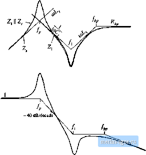 - 20 dB/deeade big, 17.24 Conttiuctioii of approximatu frequccity гс.чроше for a harmonic trap hlitM eoiitaiiiing bypass resistor: (a) impetliinte tisymptoics, {bJ Ininsfci fimclinn asymptotes. seventh btirmcnics, v/ith a single-pole rolloff to attenuate higher-order harmonics such as the eleventh and thirteenth, is illustrated in Fig. 17.25. Power loss ill the bypass resistor can be an issue: since ff, is not part of the resonant network, significant fundamental (50 Hz or йО Hz) currents can flow through R;,,. The power l[>ss can be reduced by addition of blocking capacitor C as illustrated in Fig. 17.23(b). This capacitor is cho.sen to increase the impedance of the Р-С leg at the fundamental frequency, but have negligible effect at the higher- l4g. 17.25 A haimonic trap filter containing scries resonances tuned to the fifth atid seventh harmonics, and higfi-frcquency tolloff characteristic. i Fifih-karmonic]\ Seventh-harmonic trap trap with high- frequency rolloff |