
|
| |
|
Строительный блокнот Introduction to electronics order harmonic; frequencies. The harmonic tiap filtei iietworlc can also supply significant reacrive power to the rectifier and power system. As given by Eq. (17.10), the rectifier fundamental cunent lags the voltage, and the rectifier consumes reactive power. As seen in Fig. 17.22(a), the impedances of the series resonant tank networks are dominated by their capacitor asymptotes at low frequency. Hence, at the fundamental frequency, the filter impedance reduces to an equivalent capacitor, equal to the parallel combination of the tank capacitoni. The current through this capacitance leads the ac line voltage, and hence as mentioned in the previous chapter, the capacitor is a source of reactive power. 17,5 TRANSFORMER CONNECTIONS A ftna] conventional approach to reducing the input harmonics of three-phase rectifiers is the use of phase-shifting transformer circuits. With these schemes, the low-order harmonics, such as the fifth and seventh, can be eliminated. The remaining harmonics are smaller in magnitude, and also are easier to filter. The rectifier circuit of Fig. 17.7 is known as л.six-pulse rectifier because the diode output voltage waveform contains six pulses per ac line period. The output voltage ripple has a fundamental frequency that is six times the ac line frequency. As illustrated in Fig. 17.8, the ac line current waveforms contain three steps: at any given instant, ( (() is equal to either ij, 0, or - i/. The spectrum of the current waveform contains fundamental and odd nontriplen harmonics (1, 5, 7, 11, 13,. ), whose amplitudes vary as 1/л. It is possible to shift the phase of the ac line voltage using three-phase transformer circuits. For example, in the delta-wye transformer circuit of Fig. 17.26, the transformer primary windings are driven by the primary-side line-to-line voltages, while the transformer secondaries supply the secondary-side line-to-neutral voltages. In an ideal transformer, the secondary voltage is equal to the primary voltage multiplied by the turns ratio; hence, the phasor representing the secondary voltage is in phase with the Fig, 17.26 Three-phase delta-wye transfonner conuection: (a) cireuit, (b) vollage phasoidiagram. 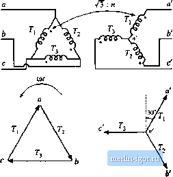 Primary voltages Secondary voltages SOurte   180- ir ir ir у у у  load .if) J L Fig, 17.27 Twelve-pulse rectifler: (a) ei uii, (b) itiput phase a cwriait waveforms. primary voltage phasor, antl is scaled in magnitude by the turns ratio. So in the delta-wye transformer connection, the secondary line-to-neutral voltages are in phase with the primary line-to-line voltages. In a balanced three-phase system, the line-t[>-line voltages are shifted in phase by 30° with respect to the line-to-iieutial voltages, and are increased in magnitude by a factor of Jb. Hence the secondary liiie-to-neutral voltages lag the primary line-to-neutral voltages by 30 . The wye-delta connection is alst) commonly used; this circuit causes the secondiuy voltages to lead the primary voltages by 30°. Many other more compiiciited transfonner circuits are known, such as the zig-zag, forked-wye, and extended-delta connections, which can lead to phase shifts of any desired imiouiit. The 30° phase shift ofthe delta-wye transformer circuit is used to advantage in the twelve-pulse rectifier circuit of Fig. 17.27(a). This circuit consists of two bridge rectifier circuits driven by 3o voltages lhal dilTer in phase by 30 . The bridge reeiilier outpuis are connected in series lo the tic Iilier intlnctor Eind Itjad. The total rectifier oiilpnt voltage vft) has a fnndamenial frequency lhat is twelve limes the ac line frequency. The inpiil phase a ac line current is the sum [ifciirrenls in three windings, and has lhe stepped waveshape illustrated in Fig. 17.27(b}. It can be shown that this waveform coniains Fourier components al the fundamental frequency and at the H , 13 , 23 , 25 ,.,. harmonic frequencies, whose amplitudes vary as Doing so is left as a homework problem. Thus, the twelve-pulse rectifier eliminates the 5* 7 , 17*, 19 ,...harmonics. An eighteen-pulse rectifier can be constructed using three six.-pulse bridge rectifiers, wilh transformer circuits lhat shift the applied voltages by 0 , + 20 , and - 20 . A twenty-four pulse rectifier requires four six-pulse bridge rectifiers, fed by voltages shifted by if. + 15, - 15°, and 30°. Up is the pulse number, ihen the rectifier produces line current harmonics of number n ~ pk ± 1, where it = 0, I, 2, 3.....If the dc current ripplecan be neglected, Ihen lhe magnitudes of the remaining current harmonics vary as l/;i. The dc-side harmonics itre Ы number pk. So by use of polyphase transformer connections and rectifier circuits having high pulse number, quite good ac line current waveforms can be obtained. As the pulse number is incrensed, the currenl waveforms approaches a sinusoid, and contains a greater number of steps having smaller amplitude. The low-order harmonics can be eliminated, and the remaining high-frequency hiumonicS are easily filtered. 17.6 SUMMARY 1. With a large dc filter inductor, the single-phase full-wave rectifier produces a square-wave line current waveform, attaining a power factor of 9t)% and 4K% THD. With .smaller value.? of inductance, these figures are degraded. In the discontinuous conduction mode, THD greater than 100%, with power factors of 55% to 65% are typical. When the capacitance is large, the power factor, THD, displacement factor, and conversion rado can be expressed as a funcdon of only the dimensionless parameter Jf. 2. In the tliree-phase ca.se. the bridge rectifier 4vith large dc filter inductor produces a stepped waveform similar to the sqtiare wave, but missing the triplen harmonics. This wavefonn has 31% THD, and leads to a power factor of 95.5%. Reduced dc inductor values again lead to increased THD and reduced power factor, and as L lends lo zero, the THD lends lo infinity wliile the power factor tends to zero. Iti practice, lhe minimum effective seiies inductance is limited by the power system source inductance. 3. With a large dc inductor, phase control does not influence the distorlion factor or THD, but does lead to a lagging futidamental currenl and decreased displacement factor. Phase-conirolled rectifiers and inverters are consumers of reactive power. 4. If lhe load is capable of snpplying power, then the phase-controlled rectifier can become an itiverter. The delay angle a is greater than SO , and the output voltage polarity is reversed with respect to rectifier opera-don. The maximuiu delay angle is limited by commutation failure to a value less than [Щ) . 5. Harmonic trap fillers and niultipulse-rectifieiVpolyphase transformer circuits find application in high-power applications where their large size and weight are less of a consideradon thaa their low cost. In the harmonic trap tiller, seiies resonant tank circuits are tuned to the offending harmonic frequencies, and shunt the harmonic currents away from Ihe utility power network. Parallel resonances may cause unwanted peaks in the filler transfer function. Operation of these filters may be understood using the alge-bra-on-lhe-graph method, and computer simulations can be used to refine lhe accuracy of the analysis or design. Rectifiers of higher pulse tiumber can also yield improved curretit waveforms, whose harmonics are of high frequency and small amplitude, aad are easily filtered. |