 | |
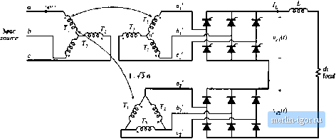
Строительный блокнот Introduction to electronics  Fig, 17,31 Tvvelve-pulse rectifier circuit, with one controlled and one uncontmlled bridge, Problem 17.7. (c) Derive an expression for Itie dc componeDl of [tie output voltage, as a function of the rms line-line inpLLt voltage, the delay angle Ct, and lhe lurns ratio u. <d) Over what range of a Is your expression of pan (c) valid? What ouipui voltages can be produced by this rectifier? ПЯ For the twelve-pulse rectifier circuii of Fig. 17.27(a), determine the Fourier coefficients, for the funda- mental through the thirteenth harmonic, of the primary-sidecurrents l (t) and tgj(). as well as for the ac line ctirrent ) (() Express your results in terms of the turns ratio n and the dc load cnrrent 1. You may assume that the dt filler inductance L is large and that the transformers are ideal. 17.9 The single-phase controlled-hridge rectifier tjf Fig. 17.32 operates in the ctmtinuous ctrnductitm mode. It is desired lo regulate the luad voltage v(l) in the presence of slow variations in the amplitude of the sinusoidal input voltage c((). Hence, a controller musl be designed that varies the delay angle a such that v(t) is kept constant, and it is of interest to derive a small-signal at model for the dt side of the rectifier circnit. () (f) с ±z уО) 4 * dc load Fig. 17.32 Single-phase controlled rectilier. Problem 17.9. (a) Skelch Vj(0 and v{t), and label the delay angle a. (b) Use the circuii averaging method to determine the small-signal transfer functions a(i) control-to-output transfer function line-to-oulput transfer function vis) as well as the steady-state relationship Vj-(V..A) where a{0 = A + a(t) v(t)=V + t(l) v,{t)[v,+v{i)) sin m You may assume that the frequencies of the variations in Ci, v, and are much slower that the ac line frequency tu, and that the inductor current ripple is small. This page intentionally left blank |